Table of Contents
Advertisement
Quick Links
Advertisement
Table of Contents

Subscribe to Our Youtube Channel
Related Manuals for IWAKI PUMPS APN-110 Series


Summary of Contents for IWAKI PUMPS APN-110 Series
- Page 1 Iwaki Air Pump APN-110 Instruction manual Thank you for choosing our product. Please read through this instruction manual before use. This instruction manual describes important precautions and instructions for the product. Always keep it on hand for quick reference. © 2010 IWAKI CO.,LTD.
-
Page 2: Order Confirmation
Order confirmation Open the package and check that the product conforms to your order. If any problem or inconsistency is found, immediately contact your distribu- tor. a. Check if the delivery is correct. Check the nameplate to see if the information such as model codes, discharge capacity and discharge pressure are as ordered. -
Page 3: Table Of Contents
Contents Order confirmation ..................... 2 Safety instructions ............... 5 WARNING ......................6 CAUTION ......................7 Precautions for use ..................9 Overview ..................12 Introduction .....................12 Pump structure & Operating principle ............12 Part names.......................13 Identification codes ..................14 Installation .................. 15 Pump mounting ....................15 Pipework ......................16 Tube connection ..................16 Wiring .......................17... - Page 4 Maintenance ................20 Troubleshooting ..................... 20 Inspection ....................... 22 Daily inspection ..................22 Wear part replacement .................. 23 Wear part list ....................23 Before service ..................... 23 Diaphragm replacement ................24 Valve replacement ..................25 Specification/Outer dimension ..............26 Specification ....................26 Pump .....................
-
Page 5: Safety Instructions
Safety instructions Read through this section before use. This section describes important information for you to prevent personal injury or property damage. ■ Symbols In this instruction manual, the degree of risk caused by incorrect use is noted with the following symbols. Please pay attention to the information associated with the symbols. -
Page 6: Warning
WARNING Turn off power before service Risk of electrical shock. Be sure to turn off power to stop the pump and related devices before service is performed. Electrical shock Stop operation If you notice any abnormal or dangerous conditions, suspend op- eration immediately and inspect/solve problems. -
Page 7: Caution
CAUTION Qualified personnel only The pump should be handled or operated by qualified personnel with a full understanding of the pump. Any person not familiar with the product should not take part in the operation or maintenance of Requirement the pump. Keep electric parts and wiring dry Risk of fire or electric shock. - Page 8 Do no use a damaged power cable Risk of fire or electric shock. The cable is not replaceable. The whole pump unit needs to be replaced when the cable is damaged. Electrical shock Install a GFCI (earth leakage breaker) An electrical failure of the pump may adversely affect other de- vices on the same line.
-
Page 9: Precautions For Use
Precautions for use • Electrical work should be performed by a qualified electrician. Otherwise, personal injury or property damage may result. Caution • Do not install the pump in a place where the pump can get wet. Avoid using wet gas, or internal con- densation will build up and consequently result in the short lives of the valve and diaphragm. - Page 10 • Do not tube two or more pumps in series. It may prevent the motor from starting and lead to a burn out. • Injection point must be below the pump position. Or siphon action or back flow may result. •...
- Page 11 • Risk of burning. A pump and a pipe surface tem- perature rises high along with liquid temperature. Do not touch the pump or pipe surface directly during operation or right after operation. • Always use a suction valve to adjust an air flow. Suction valve •...
-
Page 12: Overview
Overview Pump characteristics, features and part names are described in this section. Introduction Pump structure & Operating principle The APN-110 is a diaphragm type air pump with a AC motor. The rotary motion of the motor is converted through a connecting rod to the reciprocation of the diaphragm in the pump chamber, where gas is transferred from the inlet to outlet. -
Page 13: Part Names
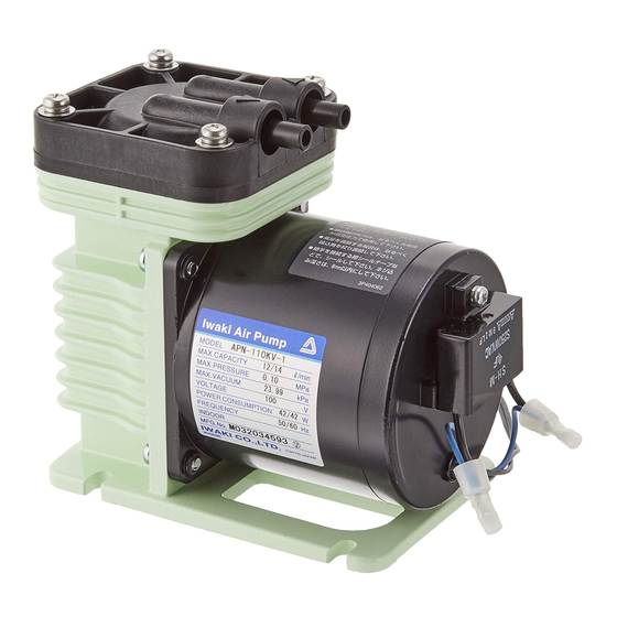
Part names Pump head Not capable of liquid transfer. Air transfer purpose only. Inlet Outlet Specification label Use the pump accord- ing to the specifica- tions on the label. Pump body (with a Base built-in drive unit) Always fix with screws. Part names... -
Page 14: Identification Codes
Identification codes The model code represents the following information. APN - S 110 K V X - 1 - 02 c d e a. Pump head No code : Single head : Dual-head with series tubing : Dual-head with parallel tubing b. -
Page 15: Installation
Installation This section describes the installation of the pump, tubing and wiring. Read through this section before work. Observe the following points • Risk of electrical shock. Be sure to turn off power to stop the pump and related devices before service is performed. •... -
Page 16: Pipework
Pipework Connect tubes to the pump. Tube end (Side view) Before operation • Cut the tube ends flat. Tube connection a. The short tubing with the minimum bends is optimal to reduce resist- ance. b. Use vinyl tubes resistant to the pumping pressure. Tube I.D. -
Page 17: Wiring
Wiring Wiring for power source and earthing. Observe the following points • Electrical work should be performed by a qualified electrician. Conform to local electric codes. • Do not apply power other than that specified on the nameplate. Other- wise, failure or fire may result. •... -
Page 18: Operation
Operation The pump becomes ready after pipework and wiring is completed. Pump operation Before operation a. Check that the pump is firmly fixed on a mounting position. b. Check that a suction tube is connected to the inlet and a discharge tube is connected to the outlet. -
Page 19: Before A Long Period Of Stoppage (1 Week Or More)
After the pump has reached a specified stroke rate, initiate full scale operation. • Always adjust an air flow by a suction valve. • In case electric power has failed while the pump is running, switch off main power. Otherwise, the motor may not restart or may burn out depending on a line pressure at the time of power recovery. -
Page 20: Maintenance
Maintenance This section describes troubleshooting, inspection, wear part replacement, exploded views and specifications. Observe the following points • Follow instructions in this manual for replacement of wear parts. Do not disassemble the pump beyond the extent of the instructions. • Always wear protective clothing such as an eye protection, chemical resistant gloves, a mask and a face shield during disassembly, assembly or maintenance work. - Page 21 Pump Power voltage is too low. • Observe the allowable voltage operation range. unintention- Suction line pressure is higher than • Keep it lower than atmospheric ally stops. atmospheric pressure. pressure. Discharge line pressure is higher • Observe the maximum discharge than the maximum.
-
Page 22: Inspection
Inspection Perform daily and periodic inspections to keep pump performance and safety. Daily inspection Check the following points every day. If you notice any abnormal or dangerous conditions, suspend operation immediately and remove problems according to "Troubleshooting". When wear parts come to the life limit, replace them by new ones. Contact your distributor for detail. -
Page 23: Wear Part Replacement
Wear part replacement To run the pump for a long period, wear parts need to be replaced periodically. It is recommended that the following parts are always stocked for immediate replacement. Contact your nearest distributor for detail. Wear part list If pump performance has remarkably reduced, replace diaphragms and valves with new ones. -
Page 24: Diaphragm Replacement
Diaphragm replacement Unscrew all the pump head fixing Pump head Pump head screws. fixing screw Take out the pump head, valve and valve seat. Mating Valve point Remove the diaphragm fixing screw Valve seat and detach the retainer plate and dia- phragm. -
Page 25: Valve Replacement
Valve replacement Unscrew the pump head fixing screws. Take out the pump head, valve and valve seat. See page 24 for detail. Replace the old valve with new one. Pump head Always check the mating points and fit the valve and the pump head in place. Outlet Inlet Valve... -
Page 26: Specification/Outer Dimension
Specification/Outer dimension Specification Information in this section is subject to change without notice. ■ Pump 50/60Hz Lowest Connection Max air Model code discharge Weight starting flow vacuum Tube Thread pressure temp. APN-110 KV/LV 12/14 2.5kg L/min APN-110 KE/LE 0.10 24.00 APN-P110 KV/LV 24/28 ø8×ø5... -
Page 27: Outer Dimension
Model KV/LV KE/LE Parts Pump head GFRPP Diaphragm EPDM Reed valve Valve seat GFRPP Retainer plate GFRPPS Screw Stainless steel GFRPP : Glass fiber reinforced polypropylene : Fluorine-contained rubber EPDM : Ethylene propylene diene monomer GFRPPS : Glass fiber reinforced polypropylene sulfide Outer dimension ■... -
Page 28: Apn-P110
■ APN-P110 ■ APN-S110 Specification/Outer dimension... -
Page 29: Performance Curves
Performance curves ■ APN-110 Vacuum 74.65kPa [abs] Vacuum 87.98kPa [abs] Discharge pressure Vacuum 101.3kPa [abs] (MPa) AIR FLOW (L/min) Vacuum pressure (kPa) [abs] Discharge pressure 0MPa ■ APN-P110 Vacuum 74.65kPa [abs] Vacuum 87.98kPa [abs] Discharge pressure Vacuum 101.3kPa [abs] (MPa) AIR FLOW (L/min) Vacuum pressure... -
Page 30: Part Names & Structure
Part names & Structure ■ APN-110 21 63 Part names Q'ty Part names Q'ty Pump head Connecting rod Valve Bracket Valve seat Con rod unit Diaphragm Motor Retainer plate Set screw Eccentric shaft Screw with washer Bearing Screw Under retainer plate Screw with washer Specification/Outer dimension... -
Page 31: Apn-P110
■ APN-P110 21 63 Part names Q'ty Part names Q'ty Pump head Connecting rod Valve Bracket Valve seat Con rod unit Diaphragm Motor Retainer plate Set screw Eccentric shaft Screw with washer Bearing Screw Under retainer plate Screw with washer Specification/Outer dimension... -
Page 32: Apn-S110
■ APN-S110 40 100 21 63 Part names Q'ty Part names Q'ty Pump head Bracket Valve Con rod unit Valve seat Motor Diaphragm Set screw Retainer plate Screw with washer Eccentric shaft Screw Bearing Screw with washer Under retainer plate Hose Connecting rod Specification/Outer dimension... - Page 33 Specification/Outer dimension...
- Page 36 TEL : (47)23 38 49 00 FAX : 23 38 49 01 China IWAKI Pumps (Guangdong) Co., Ltd. TEL : (86)750 3866228 FAX : 750 3866278 Singapore IWAKI Singapore Pte. Ltd. TEL : (65)6316 2028 FAX : 6316 3221 China GFTZ IWAKI Engineering &...
Need help?
Do you have a question about the APN-110 Series and is the answer not in the manual?
Questions and answers