Table of Contents
Advertisement
Iwaki
Electromagnetic Metering Pump
EHN-R (multi-tube connection)
Instruction manual
Thank you for choosing our product.
Please read through this instruction manual before use.
This instruction manual describes important precautions and
instructions for the product. Always keep it on hand for quick
reference.
2008 IWAKI CO., LTD.
Advertisement
Table of Contents

Subscribe to Our Youtube Channel
Related Manuals for IWAKI PUMPS EHN-B16


Summary of Contents for IWAKI PUMPS EHN-B16
- Page 1 Iwaki Electromagnetic Metering Pump EHN-R (multi-tube connection) Instruction manual Thank you for choosing our product. Please read through this instruction manual before use. This instruction manual describes important precautions and instructions for the product. Always keep it on hand for quick reference.
- Page 2 Open the package and check that the product conforms to your order. If any problem or inconsistency is found, immediately contact your distributor. a. Check if the delivery is correct. Check the nameplate to see if the informa- Iwaki Metering Pump tion such as model codes, discharge capac- CAPACITY m / min...
- Page 3 Contents Safety instructions ............... 6 ......................7 ......................8 ..................10 Overview ..................12 .....................12 ..................13 .......................16 ..................19...
- Page 4 Installation .................. 21 ....................21 ......................22 ......................27 Operation ..................33 .................... 33 ................43...
- Page 5 Maintenance ................64 ..................... 65 ....................... 67 .................. 68 ....................76 ..............82...
-
Page 6: Safety Instructions
Safety instructions Read through this section before use. This section describes important information for you to prevent personal injury or property damage. WARNING CAUTION Requirement Wear Caution Electrical Prohibited Do not rework Grounding protection shock or alter... - Page 7 WARNING Electrical shock Requirement Prohibited Do not rework or alter Wear protection Prohibited Prohibited...
- Page 8 CAUTION Requirement Prohibited Caution Prohibited Caution Prohibited Requirement...
- Page 9 Prohibited Grounding Electrical shock Requirement Prohibited Requirement Caution...
- Page 10 Caution – Caution Caution Caution Caution...
- Page 11 Caution Caution Caution Requirement Caution...
-
Page 12: Pump Structure & Operating Principle
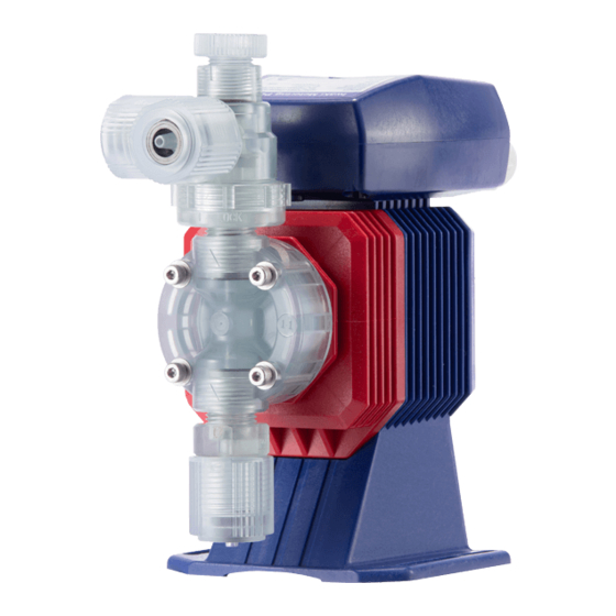
Overview Pump characteristics, features and part names are described in this section. Pump structure & Operating principle The EHN series is a diaphragm metering pump which consists of a pump head, a drive unit, and a control unit. A diaphragm is directly driven by electro- magnetic force. -
Page 13: Manual Mode
Features Manual mode Run/stop the pump by the start/stop key. A stroke rate (MAN speed) can be changed in the range of 1-360spm by the up and down keys at any time during operation or stop. See page 46 for detail. Stop Stop... -
Page 14: Ext Mode
EXT mode Pulse signal input Pump operation 1 2 3 4 5 1 2 3 4 5 Pulse signal input Pump operation 1 2 3 4 5 1 2 3 4 5 1 2 3 4 5 1 2 3... -
Page 15: Control Functions
Pulse signal input 1 2 3 4 5 1 2 3 4 5 1 2 3 4 5 Pump operation Control functions STOP signal input Pump operation Stop STOP signal input Pump operation Stop Stop... - Page 16 Pump...
-
Page 17: Operational Panel
Operational panel STROKE RATE... -
Page 19: Pump/Drive Units
The model codes of the pump/drive units and the control unit represent the fol- lowing information. Pump/Drive units EHN - B 11 VC M K R - e f g h... - Page 20 Control unit EHNC - B R -...
-
Page 21: Installation
Installation Installation of the pump, tubing, and wiring are described in this section. Select the optimal installation location and mount the pump. -
Page 22: Tube Connection
Connect tubes to the pump and install a check valve. Tube connection... -
Page 25: Check Valve Mounting
Check valve mounting Install an attached/optional check valve to the pump for the prevention of a check valve. -
Page 27: Power Voltage/Earthing
Wiring for a power voltage, earthing and an external signal. Power voltage/Earthing... - Page 28 POWER POWER TIME TIME...
-
Page 29: Signal Wire Connection
Signal wire connection... -
Page 33: Operation
Operation This section describes pump operation and programming. Run the pump after pipework and wiring is completed. rate adjustment before starting operation. Points to be checked Before operation, check if:... - Page 34 ° Degassing The gas in the pump and tubing is the obstacle to liquid delivery and needs to be expelled before the pump is started. Especially:...
- Page 35 STROKE RATE STROKE RATE STROKE RATE...
- Page 37 STROKE RATE STROKE RATE STROKE RATE...
-
Page 38: Flow Rate Adjustment
Flow rate adjustment... - Page 39 Fixed stroke rate 360spm Fixed stroke rate 360spm (Stroke rate is fixed at 100%.) (Stroke rate is fixed at 100%.) 270spm 270spm (Stroke rate is fixed at 75%.) (Stroke rate is fixed at 75%.) 180spm 180spm (Stroke rate is fixed at 50%.) (Stroke rate is fixed at 50%.) Stroke length adjustment Stroke length adjustment...
- Page 40 STROKE RATE STROKE RATE STROKE RATE STROKE RATE STROKE RATE...
- Page 41 Fixed stroke rate Stroke length adjustment STROKE RATE STROKE RATE...
-
Page 42: Before A Long Period Of Stoppage (One Month Or More)
Before a long period of stoppage (one month or more) - Page 43 Operation at each mode is individually set and controlled by keypad operation. Select a proper mode to make optimal operation.
- Page 44 Power ON Manual mode MAN speed Bounce threshold Manual operation Stop signal entry STOP function ON with the signal OFF with the signal Pump stops Pump runs...
- Page 45 EXT mode EXT display selection spm indication spm selected EXT indication EXT selected Multiplier/Divisor selection Multiplier/Divisor setting Divisor Multiplier Divisor selected Multiplier selected EXT mode EXT mode Manual (stop) Manual (run) (EXT indication) (spm indication) 3 sec. 3 sec. 3 sec. 3 sec.
-
Page 46: Manual Operation
Manual operation STROKE RATE STROKE RATE STROKE RATE... -
Page 47: Ext Operation
STROKE RATE STROKE RATE STROKE RATE STROKE RATE EXT operation The pump operation is controlled by the external (pulse) signal. - Page 48 STROKE RATE STROKE RATE STROKE RATE...
- Page 49 STROKE RATE STROKE RATE...
- Page 50 STROKE RATE STROKE RATE STROKE RATE STROKE RATE STROKE RATE STROKE RATE...
- Page 51 STROKE RATE STROKE RATE STROKE RATE STROKE RATE STROKE RATE STROKE RATE...
- Page 52 STROKE RATE STROKE RATE STROKE RATE STROKE RATE...
- Page 53 STROKE RATE STROKE RATE STROKE RATE STROKE RATE STROKE RATE STROKE RATE STROKE RATE STROKE RATE...
- Page 54 STROKE RATE STROKE RATE STROKE RATE STROKE RATE...
- Page 55 STROKE RATE STROKE RATE STROKE RATE STROKE RATE STROKE RATE STROKE RATE...
- Page 56 STROKE RATE STROKE RATE STROKE RATE STROKE RATE...
- Page 57 STROKE RATE STROKE RATE STROKE RATE STROKE RATE STROKE RATE STROKE RATE...
-
Page 58: Stop Function
STOP function The start/stop of the pump operation can be controlled by the external stop signal. STROKE RATE STROKE RATE STROKE RATE STROKE RATE... - Page 59 STROKE RATE STROKE RATE STROKE RATE STROKE RATE STROKE RATE STROKE RATE...
- Page 60 STROKE RATE STROKE RATE STROKE RATE STROKE RATE STROKE RATE STROKE RATE...
- Page 61 STROKE RATE STROKE RATE STROKE RATE STROKE RATE...
-
Page 62: Keypad Lock
Keypad lock Keypad lock can be active in the following states for the prevention of errone- ous key operation. STROKE RATE STROKE RATE STROKE RATE... - Page 63 STROKE RATE STROKE RATE STROKE RATE STROKE RATE STROKE RATE...
-
Page 64: Maintenance
Maintenance This section describes troubleshooting, inspection, wear part... - Page 65 First check the following points. If the following measures do not help remove problems, contact us or your nearest distributor.
-
Page 67: Daily Inspection
Perform daily and periodic inspection to keep pump performance and safety. Daily inspection Check the following points. If you notice any abnormal or dangerous condi- tions, suspend operation immediately and inspect/solve problems. See the troubleshooting section as necessary. When wear parts come to the life limit, replace them with new ones. Contact us or your nearest distributor for detail. -
Page 68: Wear Part List
To run the pump for a long period, wear parts need to be replaced periodically. It is recommended that the following parts are always stocked for immediate replacement. Contact us or your nearest distributor for detail. Wear part list... -
Page 69: Before Replacement
Before replacement First release pressure from the pump head. Valve set replacement... -
Page 73: Diaphragm Replacement
Diaphragm replacement... -
Page 76: Pump Head, Drive Unit & Control Unit
Pump head, Drive unit & Control unit Do not disassemble the pump beyond the description in this manual. - Page 77 Pump head...
- Page 80 (33) (34) (34) (33)
- Page 81 Check valve (VC/VH/PC/PH/PP)
- Page 82 Information in this section is subject to change without notice. code con-...
- Page 83 Mode...
-
Page 85: Outer Dimensions
Outer dimensions (202) (47) LOCK (21) (25) 81.5 7 16 10 (204) (47) LOCK (21) 81.5 (27) 7 16 10... - Page 86 (173) (16) (21) (27) 81.5 7 16 10 (220) (47) LOCK (18) (27) 18 12...
- Page 87 (222) (46) LOCK (18) (29) 18 12 (192) (16) (18) (29)
- Page 88 (222) (47) LOCK (18) (29) 18 12 (191) (16) (18) (29) 18 12...
- Page 92 TEL: +81 3 3254 2935 FAX: +81 3 3252 8892 / IWAKI Europe GmbH Norway / IWAKI Norge AS Australia / IWAKI Pumps Australia Pty Ltd. TEL: +49 2154 9254 0 FAX: +49 2154 9254 48 TEL: +47 23 38 49 00 FAX: +47 23 38 49 01...
Need help?
Do you have a question about the EHN-B16 and is the answer not in the manual?
Questions and answers