Table of Contents
Advertisement
Quick Links
Advertisement
Table of Contents

Subscribe to Our Youtube Channel
Related Manuals for IWAKI PUMPS TD Series


Summary of Contents for IWAKI PUMPS TD Series
- Page 1 IWAKI Metering Pump TD series Instruction manual Thank you for choosing our product. Please read through this instruction manual before use. This instruction manual describes important precautions and instruc- tions for the product. Always keep it on hand for quick reference.
-
Page 2: Order Confirmation
Order confirmation Open the package and check that the product conforms to your order. If any problem or inconsistency is found, immediately contact your distributor. a. Check if the delivery is correct. Check the nameplate to see if the information such as model codes, discharge capacity and discharge pressure are as ordered. -
Page 3: Table Of Contents
Contents Order confirmation ............................2 Safety instructions ..............5 Warnings ................................ 6 Cautions ................................. 8 Precautions for use ............................ 10 Overview ...................11 Introduction ..............................11 Pump structure & Operating principle ...................... 11 Pump mechanism ............................ 12 Flow pulsation reduction mechanism ....................12 Part names .............................. - Page 4 Operation ................. 23 Before operation ............................23 Operation ..............................24 Starting procedure ........................... 24 Inverter operation ............................. 25 Start/Stop of operation ........................25 Flow rate adjustment ........................... 25 Before stoppage ............................26 Resumption after a long period of stoppage .................... 26 Maintenance ................
-
Page 5: Safety Instructions
Safety instructions Read through this section before use. This section describes important information for you to prevent personal injury or property damage. ■ Symbols In this instruction manual, the degree of risk caused by incorrect use is noted with the follow- ing symbols. -
Page 6: Warnings
WARNINGS Turn off power before service Risk of electrical shock. Be sure to turn off power to stop the pump and Requirement related devices before service is performed. Stop operation If you notice any abnormal or dangerous conditions, suspend operation immediately and inspect/solve problems. - Page 7 WARNINGS Do not stand on the pump Do not use the pump as a platform. Injury or damage may result when the pump turns over. Prohibited Do not get access to the inside of the driven unit during operation Risk of personal injury. A reciprocating diaphragm/shaft may catch the fin- ger or hand.
-
Page 8: Cautions
CAUTIONS Use specified power only Do not apply power other than that specified on the nameplate. Otherwise, failure or fire may result. Ensure the pump is properly grounded. Requirement Do not install/store the pump: • In a flammable/explosive/corrosive atmosphere. • In a dusty/humid environment. •... - Page 9 CAUTIONS Preventative maintenance Follow instructions in this manual for replacement of wear parts. Do not disassemble the pump beyond the extent of the instructions. Requirement Do not use a damaged pump Use of a damaged pump could lead to an electric shock or death. Prohibited Disposal of a used pump Dispose of any used or damaged pump in accordance with local rules...
-
Page 10: Precautions For Use
Precautions for use • Electrical work should be performed by a qualified electrician. Otherwise, personal injury or property damage may result. Caution • Shipping inspection with tap water is conducted on every pump. Be sure to dry off the pump head before operation, or residual water may cause unde- sirable reaction when having contact with some chemicals. -
Page 11: Overview
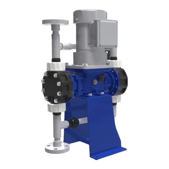
Introduction The TD series is the mechanically-driven diaphragm pump. Its pulse-reduction design en- sures low flow pulsation without the need of an air chamber. A wide selection range of wet ends allows for delivery of acid, alkaline, viscous liquid, slurry and solvent in various plants or built-in applications. -
Page 12: Pump Mechanism
Pump mechanism ■ Flow pulsation reduction mechanism The reduction mechanism consists of the two factors. One is the use of a highly-precise constant-velocity cam, which makes a trapezoidal waveform of each discharge. The other is the phase shift of two different discharge, The rear head moves out of phase with the front by 180 degrees to make a constant synthesized waveform. -
Page 13: Part Names
Part names Pump ■ TD Motor Outlet Rear pump head Gear unit Pipe unit Nameplate Front pump head Driven unit Baseplate Inlet Terminal box Oil-filler cap Oil-drain port Oil gauge Part names... -
Page 14: Identification Codes
Identification codes Each code represents the following information. TD - 2 VC FF 1 S - 02 S a. Series name b. Drive unit : High-efficiency IPM fan motor No code : High-efficiency IPM fanless motor c. Diaphragm size 01, 03, 05, 1, 2, 4, 6, 8 d. -
Page 15: Installation
Installation This section describes the installation of the pump, piping and wiring. Read through this section before installation is performed. Points to be observed Observe the following points when installing the pump: • Be sure to turn off power to stop the pump and related devices before installation is per- formed. -
Page 16: Pipework
Pipework Pipework must be done according to the following instructions to ensure the optimum per- formance, safety and service. Piping layout Arrange pump and pipework based on the following piping layout for a long period of operation. Back pressure valve (overfeeding prevention) Discharge line Relief valve... -
Page 17: Necessary Devices
Necessary devices The following devices are needed to the metering pump. Be sure to install, or personal injury or property dam- age may result. ■ Relief valve The metering pump by nature keeps working, exceeding the limit pressure of discharge line if it is blocked. This may damage the pump/piping system and burn out the motor. -
Page 18: Pump Inlet/Outlet Connections
Pump inlet/outlet connections Arrange the pump inlet and outlet according to a piping system in which the pump is incorporated. ■ Tube connection Cut the tube ends flat. Tube end (Side view) NOTE Otherwise a leak may result. Pass a tube into the fitting nut and stopper and then slide it down to the tube adapter as far as it will go. -
Page 19: Piping Precautions
Piping precautions • Foreign matters such as sand and scale may enter pipework while service is performed. They may cause fatal damage to the pump. Be sure to blow them out before operation. Also, do not apply adhesive too much or leave a screw or nut. -
Page 20: Slurry Delivery
Slurry delivery The TD can deliver slurry with some limitations. Contact us for allowable particle size and concentration. • Branch a drain line from the discharge line. Drain • Do not allow any inverted arch line in pipework where slurry can stay. •... -
Page 21: Wiring
Wiring Wiring for the inverter and the motor. Points to be observed Observe the following points during wiring work: • Do not use grid power directory to the pump. Always use an applicable inverter for pow- ering the pump, or fire may result. •... -
Page 22: Ipm Motor Terminal Box
IPM motor terminal box Use an electric conduit for the Inverter-Motor wiring. See the dimension below for detail. A conduit connection hole of I.D. 21.5mm is made on a 4mm thick terminal box. Aluminium terminal box ø21.5 Motor Unit: mm Wiring... -
Page 23: Operation
Operation This section describes pump operation and programming. Run the pump after pipework and wiring are completed. Before operation Always check the following items before the first-time operation or resuming operation after a long period of stoppage. Points to be observed Observe the following points during operation: •... -
Page 24: Operation
Operation Read this section before operation. Starting procedure Start the pump by the following procedure. Open the suction and discharge valves. Turn on the inverter power. Push the RUN key to start the pump. See page 25 for detail. NOTE Set the frequency dial to about 10Hz at the start. -
Page 25: Inverter Operation
Inverter operation See below for the basic operation of the VF-nC3M transistor inverter with default setting. See manufacturer's manual for other programming including external frequency control. Frequency display RUN key STOP key Frequency dial ■ Start/Stop of operation Use the RUN key to start and the STOP key to stop the motor. ■... -
Page 26: Before Stoppage
Before stoppage • After everyday operation, release the liquid and pressure from the pump and pipework and turn off power. • Before a long period of stoppage, flush the inside of the pump and pipework with clean water or cleaning liq- uid. -
Page 27: Maintenance
Maintenance This section describes troubleshooting, maintenance, wear part replace- ment, exploded views and specifications. Points to be observed Observe the following points during maintenance work: • Follow instructions in this manual for replacement of wear parts. Do not disassemble the pump beyond the extent of the instructions. - Page 28 States Possible causes Solutions gaseous liquid Take measures to reduce gas. a suction line (imperfect Check for an imperfect joint/sealing and Air ingress joint or sealing) retighten as necessary. from: Refill the supply tank. Degassing is required an empty tank before resuming operation.
-
Page 29: Inspection
Maintenance of IPM motor An IPM gear motor used in the TD series pump is the combination of a motor and a reduction gear unit, and the NLGI #0 extreme pressure lithium base grease is used in the gear unit. This long life grease can be used up to 10,000 hours of operating time or 3-5 years of useful life, but then needs replaced after either period has passed. -
Page 30: Oil Replacement (Drive Unit)
NOTE • Tighten the pump head bolts (parts# 20) when a leak is found from the pumphead-bracket seal. See the exploded view pages for the rated tightening torque at each pump model. If it can't stop a leak, replace the diaphragm. -
Page 31: Replacement Procedure
■ Replacement procedure Prepare a container to receive used oil in advance. Remove the oil cap. Oil cap Remove the drain plug. Use a container to collect used oil. Drain plug Replace the drain plug after the drive unit is emptied. Remove old seal tape from the drain-plug threads and apply new one before refitting the plug. -
Page 32: Wear Part Replacement
Wear part replacement To run the pump for a long period, wear parts need to be replaced periodically. Contact your distributor with the following information for wear part replacement. 1. Part names and part number (see the "Exploded view" section.) 2. -
Page 33: Before Assembly/Disassembly
Before assembly/disassembly • Inch the motor or rotate the motor fan by hand to extend the pump shaft to the maximum length when remov- ing the diaphragm. • Inch the motor or rotate the motor fan by hand to contract the pump shaft to the minimum length when replac- ing the pump head to the bracket. -
Page 34: Exploded View
Exploded view Pump head ■ TD-01/-03 VC/V6 Flange : FF2 Flange : FF1 Tube : HH3 Union : UU3 Front head CAUTION Observe the Rear head mounting direction. Valve set 216* Rotate an- ticlockwise to remove diaphragm. Pump shaft Valve set Retainer Diaphragm Apply the specified... - Page 35 Parts list Part names # of parts Materials Estimated life Pump head Valve 8000hrs or 1 YR Alumina ceramics SUS316 Valve guide 8000hrs or 1 YR Valve seat 8000hrs or 1 YR Valve gasket PTFE 8000hrs or 1 YR O ring 8000hrs or 1 YR EPDM Fitting...
-
Page 36: Td-05/-1 Vc/V6/Vs
■ TD-05/-1 VC/V6/VS Flange : FF2 Flange : FF1 Tube : HH3 Union : UU3 Front head Rear head Valve set 217* 214* CAUTION Observe the mount- ing direction. Valve set Rotate anticlockwise to remove diaphragm. CAUTION Observe the mount- ing direction. - Page 37 Parts list Part names # of parts Materials Estimated life Pump head Valve 8000hrs or 1 YR Alumina ceramics SUS316 SUS316 Valve guide 8000hrs or 1 YR Valve seat 8000hrs or 1 YR EPDM SUS304 Valve gasket PTFE 8000hrs or 1 YR O ring 8000hrs or 1 YR EPDM...
-
Page 38: Td-01/-03 Vs
■ TD-01/-03 VS Flange : FF2 Flange : FF1 Tube : HH3 Union : UU3 Front head CAUTION Rear head Observe the mount- Valve set ing direction. 216* Rotate an- ticlockwise to remove diaphragm. Pump shaft Valve set Retainer Diaphragm CAUTION Apply the specified Observe the mount-... - Page 39 Parts list Part names # of parts Materials Estimated life Pump head Valve 8000hrs or 1 YR SUS316 Valve guide 8000hrs or 1 YR Valve seat 8000hrs or 1 YR SUS304 Valve gasket PTFE 8000hrs or 1 YR O ring EPDM 8000hrs or 1 YR Fitting...
-
Page 40: Td-2/-4/-6/-8 Vc/V6/Vs
■ TD-2/-4/-6/-8 VC/V6/VS Rear head Front head CAUTION Observe the mount- ing direction. 217* 214* CAUTION Observe the mount- ing direction. Rotate anticlockwise to remove diaphragm. Pump shaft Retainer Apply the specified grease onto the sur- Diaphragm face. See page 33 for detail. - Page 41 Parts list Part names # of parts Materials Estimated life Pump head Valve 8000hrs or 1 YR Alumina ceramics SUS316 SUS316 Valve guide 8000hrs or 1 YR Valve seat 8000hrs or 1 YR SUS304 Valve gasket PTFE 8000hrs or 1 YR O ring 8000hrs or 1 YR EPDM...
-
Page 42: Td-01/-03 S6
■ TD-01/-03 S6 Flange : FF2 Flange : FF1 Hold the fitting (#9) with a span- ner when tightening the pipe unit (#70/71) to the pump head. Front head Rear head Valve set CAUTION Observe the mount- 216* ing direction. CAUTION Observe the mount- Valve set... - Page 43 Parts list Part names # of parts Materials Estimated life Pump head SUS316 Valve 8000hrs or 1 YR SUS316 Valve guide 8000hrs or 1 YR SUS316 Valve seat 8000hrs or 1 YR SUS316 Valve gasket PTFE 8000hrs or 1 YR Fitting SUS316 Hexagon bolt...
-
Page 44: Td-05/-1 S6
■ TD-05/-1 S6 Flange : FF2 Flange : FF1 Hold the fitting (#9) with a span- ner when tightening the pipe unit (#70/71) to the pump head. Front head Rear head Valve set 217* CAUTION 214* Observe the mount- ing direction. Rotate an- ticlockwise to remove... - Page 45 Parts list Part names # of parts Materials Estimated life Pump head SUS316 Valve 8000hrs or 1 YR SUS316 Valve guide 8000hrs or 1 YR SUS316 Valve seat 8000hrs or 1 YR SUS316 Valve gasket PTFE 8000hrs or 1 YR Fitting SUS316 Hexagon bolt...
-
Page 46: Td-2/-4/-6/-8 S6
■ TD-2/-4/-6/-8 S6 Rear head Front head 214* Valve set CAUTION Observe the mount- ing direction. 217* Rotate anticlock- wise to remove diaphragm. Valve set CAUTION Observe the mount- Pump shaft ing direction. Retainer Apply the specified Diaphragm grease onto the sur- face. - Page 47 Parts list Part names # of parts Materials Estimated life Pump head SUS316/SCS14 Valve 8000hrs or 1 YR SUS316 Valve guide 8000hrs or 1 YR SUS316 Valve seat 8000hrs or 1 YR SUS316 Valve gasket PTFE 8000hrs or 1 YR Valve support SUS316 Hexagon bolt...
-
Page 48: Specifications/Outer Dimensions
Specifications/Outer dimensions Specifications Information in this section is subject to change without notice. ■ Pump TD-VC/-V6/-S6 TD-01/-M01 TD-03/-M03TD-05/-M05 TD-1/-M1 TD-2/-M2 TD-4/-M4 TD-6/-M6 TD-8/-M8 Flow rate* l/min 0.15 Max discharge press. Repeatability ±2% FS Linearity ±2% FS 300mPa•s Max allowable viscosity* 500mPa•s (Newtonian liquid) 500mPa•s... -
Page 49: Inverter
TD-VC/-V6/-S6/-VS TD-01/-M01 TD-03/-M03TD-05/-M05 TD-1/-M1 TD-2/-M2 TD-4/-M4 TD-6/-M6 TD-8/-M8 Flow control method Motor rpm control Turndown ratio 1:10 Control Frequency 6-60 10-60 range Stroke rate* 12-120 7-72 12-120 15-90 20-120 Reduction ratio 1:15 1:25 1:15 1:20 1:15 Stroke length Diaphragm effective dia. ø30 ø60 ø72... -
Page 50: Outer Dimensions
Outer dimensions Information in this section is subject to change without notice. ■ FF type Flange direction Flange direction Flange direction Flange direction code: 1 code: 2 code: 3 code: 4 JIS 10K gA JIS 10K gA JIS 10K gA JIS 10K gA 4×ø12 JIS10K fA... -
Page 51: Hh Type
■ HH type 4×ø12 Dimensions in mm WEM* VC/V6/VS Size TD-01 ø12 × ø18 TD-03 ø12 × ø18 TD-05 ø12 × ø18 TD-1 ø12 × ø18 WEM stands for Wet End Material code CD stands for Connection Direction code ■ UU type 4×ø12 Dimensions in mm WEM*... -
Page 52: Performance Curves
Performance curves The following performance curves are collected at each diaphragm size in operation with clean water at 25ºC and are subject to change with operating conditions and individual differences. Always measure flow rates at each frequency under actual conditions to obtain appropriate inverter setting. ■... - Page 53 ■ TD-VC/-V6 TD-2/-M2 TD-4/-M4 0.05MPa 0.05MPa 0.5MPa 1.0MPa ℓ/H ℓ/min ℓ/H ℓ/min TD-6/-M6 TD-8/-M8 0.05MPa 0.05MPa 0.4MPa ℓ/H ℓ/min 0.3MPa ℓ/H ℓ/min Specifications/Outer dimensions...
-
Page 54: Td-S6
■ TD-S6 TD-01/-M01 TD-03/-M03 0.05MPa 0.05MPa 1.0MPa 1.0MPa ℓ/H ℓ/min ℓ/H ℓ/min 0.40 0.25 0.35 0.20 0.30 0.25 0.15 0.20 0.10 0.15 0.10 0.05 0.05 TD-05/-M05 TD-1/-M1 0.05MPa 0.05MPa 1.0MPa 1.0MPa ℓ/H ℓ/min ℓ/H ℓ/min 1.50 1.25 1.00 0.75 0.50 0.25 Specifications/Outer dimensions... - Page 55 ■ TD-S6 TD-2/-M2 TD-4/-M4 0.05MPa 0.05MPa 1.0 MPa 0.5MPa ℓ/min ℓ/H ℓ/min ℓ/H TD-6/-M6 TD-8/-M8 0.05MPa 0.05MPa 0.4MPa ℓ/min 0.3MPa ℓ/H ℓ/min ℓ/H Specifications/Outer dimensions...
-
Page 56: Td-Vs
■ TD-VS TD-01/-M01 TD-03/-M03 0.05MPa 0.05MPa ℓ/H ℓ/min ℓ/H ℓ/min 1.0MPa 1.0MPa 1.50 0.30 1.25 0.25 1.00 0.20 0.75 0.15 0.50 0.10 0.25 0.05 TD-05/-M05 TD-1/-M1 0.05MPa 0.05MPa ℓ/H ℓ/min ℓ/H ℓ/min 1.0MPa 1.0MPa 1.25 1.00 0.75 0.50 0.25 Specifications/Outer dimensions... - Page 60 IWAKI Norge AS TEL : (47)23 38 49 00 FAX : 23 38 49 01 China IWAKI Pumps (Guangdong) Co., Ltd. TEL : (86)750 3866228 FAX : 750 3866278 Singapore IWAKI Singapore Pte. Ltd. TEL : (65)6316 2028 FAX : 6316 3221 China GFTZ IWAKI Engineering &...
Need help?
Do you have a question about the TD Series and is the answer not in the manual?
Questions and answers