Table of Contents
Advertisement
Quick Links
Iwaki
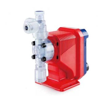
Electromagnetic Metering Pump
EJ-B(S) (Asia)
Instruction manual
Thank you for choosing our product.
Please read through this instruction manual before use.
This instruction manual describes important precautions and
instructions for the product. Always keep it on hand for quick
reference.
2013 IWAKI CO., LTD.
Advertisement
Table of Contents

Related Manuals for IWAKI PUMPS EJ-B


Summary of Contents for IWAKI PUMPS EJ-B
- Page 1 Iwaki Electromagnetic Metering Pump EJ-B(S) (Asia) Instruction manual Thank you for choosing our product. Please read through this instruction manual before use. This instruction manual describes important precautions and instructions for the product. Always keep it on hand for quick reference.
-
Page 2: Order Confirmation
Order confirmation Open the package and check that the product conforms to your order. If any problem or inconsistency is found, immediately contact your distribu- tor. a. Check if the delivery is correct. Check the nameplate to see if the information such as model codes, dis- charge capacity and discharge pressure are as ordered. -
Page 3: Table Of Contents
Contents Order confirmation ..................... 2 Safety instructions ............... 6 Warning ......................7 Caution ......................8 Precautions for use ..................10 Overview ..................12 Introduction .....................12 Pump structure & Operating principle ............12 Features .......................13 Operational functions ..................13 Manual mode ....................13 Part names.......................14 Pump......................14 Operational panel ..................15 Basic displays &... - Page 4 Operation ..................26 Before operation .................... 26 Points to be checked .................. 26 Retightening of pump head fixing bolts ............26 Use of hexagon wrench instead of a torque wrench ......27 Degassing ....................27 Flow rate adjustment .................. 30 Before a long period of stoppage (one month or more) ......
- Page 5 Exploded view ....................47 Pump head & Drive unit ................47 Pump head ....................48 Specifications/Outer dimensions ..............49 Specifications ..................... 49 Pump unit ....................49 Control unit .................... 50 Power cable ................... 50 Pump colour ..................50 Outer dimensions..................51 EJ-B09/-B11/-B16/-B21 VC/VH ..............51 EJ-B11/-B16/-B21 TC ................52 Contents...
-
Page 6: Safety Instructions
Safety instructions Read through this section before use. This section describes important information for you to prevent personal injury or property damage. ■ Symbols In this instruction manual, the degree of risk caused by incorrect use is noted with the following symbols. Please pay attention to the information associated with the symbols. -
Page 7: Warning
WARNING Turn off power before service Risk of electrical shock. Be sure to turn off power to stop the pump and related devices before service is performed. Electrical shock Stop operation If you notice any abnormal or dangerous conditions, suspend op- eration immediately and inspect/solve problems. -
Page 8: Caution
CAUTION Qualified personnel only The pump should be handled or operated by qualified personnel with a full understanding of the pump. Any person not familiar with the prod- uct should not take part in the operation or maintenance of the pump. Requirement Use specified power only Do not apply power other than that specified on the nameplate. - Page 9 Do not use the pump in a wet location The pump is not waterproof. Use of the pump in wet or extremely humid locations could lead to electric shock or short circuit. Prohibited Grounding Risk of electrical shock! Always properly ground the pump. Con- form to local electric codes.
-
Page 10: Precautions For Use
Precautions for use • Electrical work should be performed by a qualified electri- cian. Otherwise, personal injury or property damage could result. Caution • Do not install the pump: –In a flammable atmosphere. –In a dusty/humid place. –In direct sunlight or wind & rain. –... - Page 11 • Use care handling the pump. Do not drop. An impact may affect pump performance. Do not use a pump that has been damaged to avoid the risk of electrical damage or shock. • The pump has a rating of IP65 equivalent, but is not water- proof.
-
Page 12: Overview
Overview Pump characteristics, features and part names are described in this section. Introduction Pump structure & Operating principle The EJ series is a diaphragm metering pump which consists of a pump head and a drive unit with a built-in controller. A diaphragm is directly driven by elec- tromagnetic force. -
Page 13: Features
Features ● Multivoltage operation The EJ series is a multivoltage type (100-240VAC) and can be selected with- out local power limitations. ● High turndown ratio Digitally-controlled spm range is 1-360spm. ● IP rating of 65 equivalent This pump is not waterproof. Protect the pump with a cover when installing it out of doors. -
Page 14: Part Names
Part names Pump Air vent port Always connect a tube. Be sure to return the tube end to a supply tank or a container. Adjusting screw A circumferential direction of the Used for opening the air vent port. port can be changed up to 90 degrees counterclockwise from the original position. -
Page 15: Operational Panel
Operational panel Display Stroke rate and operational status are shown here. ON LED Lights as turning on power START and flashes at each stroke. STOP UP key Used for increasing numeric val- ues. If this key is kept pressed, the value rises faster. -
Page 16: Basic Displays & Pump States
■ Basic displays & Pump states Shows a pump speed in spm. The spm flashes during operation in MAN mode. The indication changes to "- - -" when the pump enters maintenance mode. Represents keypads are locked. ON LED flushes Display info ON LED lights (in sync with each shot) -
Page 17: Identification Codes
Identification codes The model codes of the pump/drive units represent the following information. EJ - B 11 VC 1 J S _ - _ _ e f g h a. Series name EJ: Multivoltage electromagnetic metering pump b. Drive unit (Average power consumption) B: 15W c. -
Page 18: Installation
Installation This section describes the installation of the pump, tubing and wiring. Read through this section before work. Observe the following points when installing the pump. • Risk of electrical shock. Be sure to turn off power to stop the pump and related devices before service is performed. -
Page 19: Plumbing
Plumbing Connect tubes to the pump and install a check valve. Before operation Tube end (side view) • Cut the tube ends flat. Necessary tools • Adjustable wrench or a spanner Tube connection a. Pass a tube into the fitting nut and Tube Fitting nut stopper and then slide it down to the... - Page 20 Connect tubes into the inlet and outlet. Outlet Tube Inlet Tube Connect an air bleed tube into the Air vent port air vent port. Route back the other tube end to a Air bleed tube supply tank or a container. Determine an air vent port direction.
-
Page 21: Check Valve Mounting
Check valve mounting Install an optional check valve to the EJ for the prevention of a back flow, siphon and overfeeding. In the following cases be sure the check valve is installed. • A suction side liquid level is higher than a discharge side or an injection point at atmospheric pressure. - Page 22 Mount a check valve at the discharge tube end. * The CAN check valve has the R1/2 and R3/8 thread connections as well as an O.D.9mm tube connection. Cut off an unused part and adjust the connection length as necessary. CAN check valve R1/2 O.D.9mm...
-
Page 23: Wiring
Wiring Wiring for a power voltage, earthing and an external signal. Observe the following points during wiring work. • Electrical work should be performed by a qualified electrician. Always observe local electric codes. • Observe the rated voltage range, or the electrical circuit in the control unit may fail. - Page 24 NOTE • Do not share a power source with a high power device which may generate surge voltage. Otherwise an electronic circuit may fail. The noise caused by an inverter also affects the circuit. • Energize the pump with a power voltage via a mechanical relay or switch. Do not fluctuate the voltage, or CPU may malfunction.
- Page 25 Precautions for ON-OFF control by a mechanical relay This pump is equipped with CPU. Observe the following points when ON- OFF control is performed: • Do not turn ON/OFF power voltage more than six times per hour. • When using a mechanical relay for ON-OFF operation, its contact capac- ity should be 5A or more.
-
Page 26: Operation
Operation This section describes pump operation and programming. Run the pump after plumbing and wiring are completed. Before operation Check a flow rate, tubing and wiring. And then perform degassing and flow rate adjustment before starting operation. Points to be checked Before operation, check if... -
Page 27: Use Of Hexagon Wrench Instead Of A Torque Wrench
■ Use of hexagon wrench instead of a torque wrench Fasten the fixing bolts as tight as can be by the hand with the straight long part of a hexagon wrench (a) and further turn the bolts clockwise 90 degrees with the short part (b). - Page 28 Points to be checked Air bleed tube • An air bleed tube is connected to the pump. Turn on power. The LED lights and a display related to the current mode appears on the screen. * The pump waits in the MAN mode when the power is turned ON with a default setting or calls START STOP...
- Page 29 Push the start/stop key and run the pump for more than ten minutes. START START STOP STOP Push the start/stop key and stop the pump. Rotate the adjusting screw clockwise to close the air vent port. Check liquid is discharged. *Degassing is required again if the pump does not discharge liquid.
-
Page 30: Flow Rate Adjustment
Flow rate adjustment A flow rate can be adjusted only by changing a stroke rate (stroke length adjustment is not available). A stroke rate can be set by keypad operation from 1 to 360spm. The relation between a flow rate* and a stroke rate is shown as below. - Page 31 Use the UP key to adjust a stroke rate. • spm increases as pushing the UP keys. • Press and hold the key for three seconds for quick increment. Quick increment stops at 360spm. 360spm skips to 1spm when the key is released and pushed once.
-
Page 32: Before A Long Period Of Stoppage (One Month Or More)
Before a long period of stoppage (one month or more) Clean wet ends and the inside of tubing. • Run the pump with clean water for about 30 minutes to rinse chemicals off from the pump head and piping. Before unplugging the pump •... -
Page 33: Operation Programming
Operation programming Operation at each mode is individually set and controlled by keypad operation. Select a proper mode to make optimal operation. Programming flow Maintenance mode 3 sec. Power ON Power ON while the UP key is pressed. The maintenance mode will come up after 3 seconds. -
Page 34: Manual Operation
Manual operation Turn on power. The LED lights and a display related to the current mode appears on the screen. * The pump waits in the manual mode when the power is turned ON with a default set- START ting or calls up the last selected mode or STOP condition. -
Page 35: Keypad Lock
Keypad lock Keypad lock can be active in the MAN mode for the prevention of erroneous key operation. The "LOCK" indication appears while keypads are locked. NOTE Any key operation is not acceptable when the keypads are locked. In an emergency, unplug the pump to stop operation. -
Page 36: Maintenance
Maintenance This section describes troubleshooting, inspection, wear part replacement, exploded views and specifications. Important • Follow instructions in this manual for replacement of wear parts. Do not disassemble the pump beyond the extent of the instructions. • Always wear protective clothing such as an eye protection, chemical re- sistant gloves, a mask and a face shield during disassembly, assembly or maintenance work. -
Page 37: Troubleshooting
Troubleshooting First check the following points. If the following measures do not help removing problems, contact us or your nearest distributor. States Possible causes Solutions The pump Power voltage is too low. • Observe the allowable voltage does not run range of 90-264VAC ( blank LED The pump is not powered. -
Page 38: Inspection
Inspection Perform daily and periodic inspection to keep pump performance and safety. Daily inspection Check the following points. Upon sensing abnormality, stop operation immedi- ately and remove problems according to "Troubleshooting". When wear parts come to the life limit, replace them with new ones. Contact us or your nearest distributor for detail. -
Page 39: Wear Part Replacement
Wear part replacement To run the pump for a long period, wear parts need to be replaced periodically. It is recommended that the following parts are always stocked for immediate replacement. Contact us or your nearest distributor for detail. Precautions •... -
Page 40: Before Replacement
Before replacement First release pressure from the pump head. Stop the pump operation. Rotate the adjusting screw two revolutions anticlockwise to open the air vent port. NOTE Do not rotate it three revolutions or more. Otherwise, the adjusting screw may come off with solution spray. -
Page 41: Valve Set Replacement
Valve set replacement ■ Discharge valve set disassembly/assembly Necessary tools • Adjustable wrench or spanner • 21mm box wrench • A pair of tweezers *Unfix the pump base before disassembly. Loosen the fitting nut to remove a dis- Air bleed tube charge tube and an air bleed tube. - Page 42 Remove the air vent body B with a 21mm box wrench. Air vent body B Pull out the valve set by a pair of tweezers. Place a new valve set into the pump head and Air vent body B screw the air vent body B through the lock nut. * Be careful not to misarrange the valve set or place Lock nut upside down.
-
Page 43: Suction Valve Set Dismantlement/Assembly
■ Suction valve set disassembly/assembly NOTE Be careful not to drop the valve set. Remove the fitting nut and the suction tube. NOTE Wash out residual liquid or substances. Fitting nut Suction tube Remove the fitting by an adjustable wrench or a spanner. -
Page 44: Diaphragm Replacement
Diaphragm replacement Necessary tools • Adjustable wrench or spanner • Hexagon wrench • Torque wrench NOTE • Pay attention not to loose diaphragm spacers. Always apply a proper number of dia- phragm spacers. 0 or a few diaphragm spacers are inserted between the retainer and plunger for the adjustment of diaphragm location. - Page 45 Push the UP key to extend the pump shaft to the full. * LCD flashes wile the shaft is extended. START START STOP STOP NOTE • Do not extend the shaft any purposes other than the replacement of the dia- phragm.
- Page 46 Push the UP key again to contract the pump shaft to the minimum. Push the start/stop key to enter the WAIT mode. START START STOP STOP Mount the pump head. Tighten the pump head fixing bolts evenly to 2.16N•m in diagonal order. *A hexagon wrench can be used for a torque wrench.
-
Page 47: Exploded View
Exploded view Pump head & Drive unit The pump in the diagram below is completely dismantled. Do not dismantle the pump beyond the extent shown in this instruction manual. Diaphragm spacer Valve set Retainer Pump body Diaphragm Valve set Exploded view... -
Page 48: Pump Head
Pump head Part names # of parts Pump head Fitting Fitting nut Air vent body B Lock nut Diaphragm Retainer Air vent body A Valve guide 10 Valve seat 11 Valve 12 Valve gasket 13 O ring 14 Diaphragm spacer Hex. -
Page 49: Specifications/Outer Dimensions
Specifications/Outer dimensions Specifications Information in this section is subject to change without notice. ■ Pump unit Flow rate Discharge Power con- Current Stroke rate Weight Model code pressure sumption value (mℓ/min) 1.14 EJ-B09 (19) EJ-B11 (30) 1-360 EJ-B16 (50) EJ-B21 (80) * The above information is based on pumping clean water at rated voltage and ambient temperature. -
Page 50: Control Unit
■ Control unit Operation mode Manual Start/Stop by key operation Setting range 1-360spm Stroke rate Spm programming UP key 7×3 LCD with one status code Monitors Green LED×1 (blinks at each shot) Buffer Non-volatile memory Power voltage* 100-240VAC 50/60Hz * Observe the allowable voltage range of 90-264VAC. Otherwise failure may result. ■... -
Page 51: Outer Dimensions
Outer dimensions ■ EJ-B09/-B11/-B16/-B21 VC/VH (219) (194) (47) LOCK (24) 36.5 76.5 9 16.5 10 Specifications/Outer dimensions... -
Page 52: Ej-B11/-B16/-B21 Tc
■ EJ-B11/-B16/-B21 TC (220) (195) (48) LOCK (24) 36.5 76.5 9 16.5 10 Specifications/Outer dimensions... - Page 53 Specifications/Outer dimensions...
- Page 56 European office / IWAKI Europe GmbH Norway / IWAKI Norge AS Australia / IWAKI Pumps Australia Pty Ltd. TEL: +49 2154 9254 0 FAX: +49 2154 9254 48 TEL: +47 23 38 49 00 FAX: +47 23 38 49 01...
Need help?
Do you have a question about the EJ-B and is the answer not in the manual?
Questions and answers