Advertisement
Quick Links
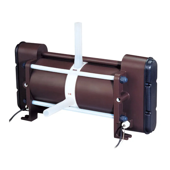
Iwaki
Pneumatic Drive Bellows Pump
FW-H series
Instruction manual
Thank you for choosing our product.
Please read through this instruction manual before use.
This instruction manual describes important precautions and instruc-
tions for the product. Always keep it on hand for quick reference.
©2011 IWAKI CO., LTD.
Advertisement

Related Manuals for IWAKI PUMPS FW-H Series


Summary of Contents for IWAKI PUMPS FW-H Series
- Page 1 Iwaki Pneumatic Drive Bellows Pump FW-H series Instruction manual Thank you for choosing our product. Please read through this instruction manual before use. This instruction manual describes important precautions and instruc- tions for the product. Always keep it on hand for quick reference.
- Page 2 Open the package and check that the product conforms to your order. If any problem or inconsistency is found, immediately contact your distributor. a. Check if the delivery is correct. Check the nameplate to see if the information such as model codes are as ordered. b.
- Page 3 Contents Safety instructions ..............5 ................................6 ................................7 ............................9 Overview ...................10 ..............................10 ..............................11 ..........................12 ............................ 14 Installation ................15 ............................15 ............................17...
- Page 4 .............................. 21 ............................. 25 Operation ................. 27 ............................27 ............................28 Maintenance ................30 ............................30 ..............................33 ........................35...
- Page 5 Safety instructions Read through this section before use. This section describes important information for you to prevent personal injury or property damage. WARNING CAUTION Requirement Wear Grounding Caution Electrical Prohibited Do not rework protection shock or alter...
- Page 6 WARNING Requirement Requirement Requirement Prohibited Do not remodel Wear protectors Requirement Caution Prohibited Requirement...
- Page 7 CAUTION Requirement Prohibited Requirement Prohibited • In Prohibited Requirement Requirement Requirement Requirement...
- Page 8 CAUTION Requirement Requirement Requirement Requirement...
- Page 9 – Caution – • Caution Caution – • Caution • • Caution • Caution • Requirement • Caution • Requirement...
- Page 10 Overview Pump characteristics, features and part names are described in this sec- tion. Pump structure & Operating principle manufacturing processes. Suction process Discharge process...
- Page 11 Pump...
- Page 12 Pump stroke Observe the maximum stroke rate of 120spm (FW-20H) or 80spm (FW-40H), or the pump can take in a large amount of air, resulting dry running. Supply air pressure range Observe the allowable supply air pressure range at each liquid temperature below. Liquid temperature range Observe the allowable liquid temperature range of 10-180 may reduce the life of the pump.
- Page 13 Operation and Stoppage • • Air exhaust port Do not narrow an air exhaust line (for example by reducing the tube I.D.). Or the residual pressure in the pump may deform the bellows. Leak sensors The sensors occasionally fails to detect leakage depending on operating conditions. Contact us for detail. Ambient temperature Observe the allowable operating ambient temperature range of 0-40 C.
- Page 14 Each code represents the following information. FW - 20 H T 1 - 01 a c d...
- Page 15 Installation This section describes the installation of the pump, piping and wiring. Read through this section before work. To operate this pump, a 5-port solenoid valve and FDC-1 controller is needed. Always install QEVs (quick exhaust valves) to secure system safety.
- Page 16 NOTE...
- Page 17 The pump has different sizes of the inlet/outlet PFA tube at each model. See the table below. Piping Pump head tube Tube fitting Pump head tube Piping Tube fitting NOTE...
- Page 18 Suction line NOTE NOTE...
- Page 19 Discharge line The pipe resistance increases as a discharge line becomes longer or the number of bends increases. In order to decrease pipe resistance, install a dampener and minimizes pulsation. Select a valve with an orifice equal to or larger than pipe I.D. A valve with a small orifice may increase the pipe resistance or easily be clogged with crystals.
- Page 20 Degassing Gas bubbles are generated when a strong acid is fed into the reaction tank or liquid is transferred through a narrow tube. If such bubbles enter the bellows, the pump runs dry, increasing stroke rate or disturbing liquid transfer. Take a proper step for degassing. In flooded suction application Bubbles go up.
- Page 21 ° ° ° • • • • Supply air port (pump) Tube Tube coupling NOTE...
- Page 22 Air line piping diagram The diagram below is a general layout of an air-line. Air source Pump a. Regulator NOTE b. The air line between the regulator and the solenoid valve c. Solenoid valve * Al...
- Page 23 d. Muffler e. The air line between the SV and QEV f. QEV Air flow Pump exhaust exhaust Quick Exhaust Valve 5-port Electrically-connected solenoid valve to the controller Compressor (air supply Air exhaust source) Pressure gauge : Air flow Filter : Air line Filtered reducing valve : Electrical wire...
- Page 24 Composite effective cross-sectional area 1. Pneumatic devices 2. Composite effective cross-sectional area If condensation is likely to occur in the air lines between the pump and SV, take the following preventive meas- ures.
- Page 25 Two 5-port double solenoid valves and the FDC-1 controller is required. • • • • Installation...
- Page 26 Wiring diagram Turn off the FDC-1 controller before wiring is performed. See the instruction manual of the FDC-1 controller as necessary.
- Page 27 Operation This section describes pump operation and programming. Run the pump after pipework and wiring are completed. long period of stoppage. NOTE NOTE...
- Page 28 The start/stop of the pump is controlled by the FDC-1 controller in MANU mode or a user PLC in AUTO mode. The procedure below is the example of starting the pump by keypad operation with the FDC-1. Starting the pump NOTE...
- Page 29 Flow rate adjustment Stoppage NOTE...
- Page 30 Maintenance mensions. • • • • First check the following points. If the following measures do not help remove problems, con- tact your distributor.
- Page 33 Perform daily and periodic inspection to keep pump performance and safety. Daily inspection Check for a leak or any other abnormality during operation. If you notice any abnormal conditions, stop opera- tion immediately and remove problems according to the "Troubleshooting" section. Replacement of wear parts is necessary at periodic intervals.
- Page 34 Wear part list To run the pump for a long period, wear parts need to be replaced periodically or when pump performance has reduced. Contact your distributor with the following information for wear part replacement.
- Page 35 Information in this section is subject to change without notice. SUS304 SUS304...
- Page 36 Outer dimension 22 [0.87"] 2-Ø19×Ø16[3/4"] AIR SUP. 2×Rc1/4 346 [13.62"] 10 [0.39"] 10 [0.39"] 458 [18.03"] 105 [4.13"] (100)[3.94"] 140 [5.51"] 22 [0.87"] 2-Ø19×Ø16[3/4"] AIR SUP. 2×Rc1/4 346 [13.62"] 10 [0.39"] 10 [0.39"] 458 [18.03"] 105 [4.13"] (100)[3.94"] 140 [5.51"]...
- Page 37 25.5 [1.00"] 2-Ø25×Ø22[1"] AIR SUP. 2×Rc3/8 434 [17.09"] 12 [0.47"] 12 [0.47"] 542 [21.34"] 143 [5.63"] (100)[3.94"] 183 [7.20"] FW-40T1 25.5 [1.00"] 2-Ø25×Ø22[1"] AIR SUP. 2×Rc3/8 434 [17.09"] 12 [0.47"] 12 [0.47"] 542 [21.34"] 143 [5.63"] (100)[3.94"] 183 [7.20"]...
- Page 38 Part names N: LEAK SENSOR 17 18 1 PTFE 8 STNLS STL 4 PTFE 4 PTFE 4 PTFE 2 STNLS STL 2 PTFE 2 SUS304 2 PPE 2 SUS304 4 SUS304 8 STNLS STL 4 SUS304 8 STNLS STL 12 STNLS STL 24 STNLS STL 12 STNLS STL 4 STNLS STL...
- Page 39 N: LEAK SENSOR 1 PTFE 8 STNLS STL 4 PTFE 4 PTFE 4 PTFE 2 STNLS STL 2 PTFE 2 SUS304 2 PPE 4 SUS304 4 SUS304 8 STNLS STL 12 STNLS STL 8 STNLS STL 12 STNLS STL 8 STNLS STL 2 SUS304 4 STNLS STL 2 SUS304...
- Page 40 17 18 N LEAK SENSOR 53 54 1 PTFE 4 PTFE 2 STNLS STL 4 PTFE 4 PTFE 2 PTFE 2 SUS304 4 SUS304 2 SUS304 8 STNLS STL 8 STNLS STL 24 STNLS STL 4 SUS304 4 STNLS STL 16 STNLS STL 4 SUS304 16 STNLS STL...
- Page 41 17 18 N LEAK SENSOR 53 54 1 PTFE 4 PTFE 2 STNLS STL 4 PTFE 4 PTFE 2 PTFE 2 SUS304 4 SUS304 8 STNLS STL 8 STNLS STL 4 SUS304 8 STNLS STL 16 STNLS STL 4 STNLS STL 16 STNLS STL 4 SUS304 2 SUS304...
- Page 42 KAZUNARI NISHIKUBO...
- Page 44 Germany / IWAKI Europe GmbH Norway / IWAKI Norge AS China (Hong Kong) / IWAKI Pumps Co., Ltd. TEL: +49 2154 9254 50 FAX: +49 2154 9254 55 TEL: +47 23 38 49 00 FAX: +47 23 38 49 01...
Need help?
Do you have a question about the FW-H Series and is the answer not in the manual?
Questions and answers