Sign In
Upload
Download
Table of Contents
Contents
Add to my manuals
Delete from my manuals
Share
URL of this page:
HTML Link:
Bookmark this page
Add
Manual will be automatically added to "My Manuals"
Print this page
×
Bookmark added
×
Added to my manuals
Manuals
Brands
Shimano Manuals
Bicycle Accessories
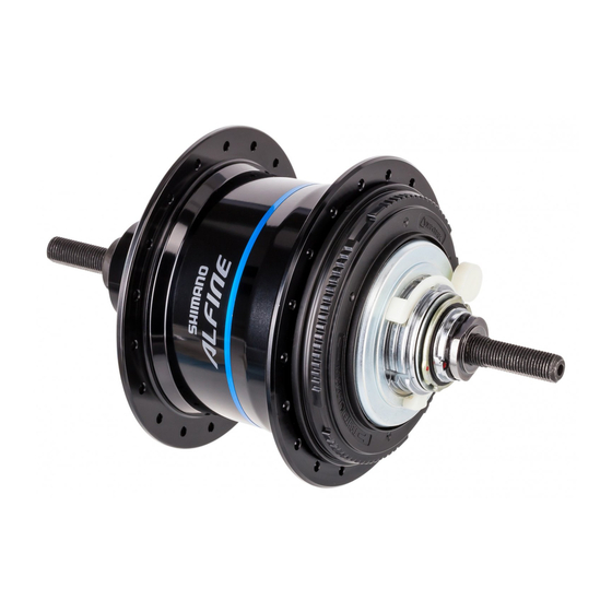
ALFINE Inter-11
Dealer's manual
Shimano ALFINE Inter-11 Dealer's Manual
Hide thumbs
1
Table Of Contents
2
3
4
5
6
7
8
9
10
11
12
13
14
15
16
17
18
19
20
21
22
23
24
25
26
27
28
29
30
31
32
33
34
35
36
37
38
39
40
41
42
43
44
45
46
47
48
49
page
of
49
Go
/
49
Contents
Table of Contents
Bookmarks
Table of Contents
Table of Contents
Important Notice
To Ensure Safety
List of Tools to be Used
Installation
Installation of the Sprocket to the Hub
Installation of the CS-S500 Sprocket with Chain Guard
Installation of the Cassette Joint to the Hub
Installation of the Disc Brake Rotor
Installation of the Hub to the Frame
Installation of the Shift Lever
Installation of the Shifting Cable
Adjustment
Adjusting the Cassette Joint
Maintenance
Replacement and Assembly of the Indicator Unit
For Internal 8-Speed (Oil Maintenance Kit: Y00298010)
For Internal 11-Speed (Oil Maintenance Kit: Y13098023)
Advertisement
Quick Links
1
Table of Contents
2
Installation
3
Installation of the Shift Lever
4
Installation of the Shifting Cable
5
Adjustment
6
Adjusting the Cassette Joint
7
Maintenance
8
For Internal 11-Speed (Oil Maintenance Kit: Y13098023)
Download this manual
(English)
ROAD
City Touring/
Comfort Bike
Inter-11
Inter-8
MTB
URBAN SPORT
Dealer's Manual
Trekking
E-BIKE
DM-SG0004-07
Table of
Contents
Previous
Page
Next
Page
1
2
3
4
5
Advertisement
Table of Contents
Need help?
Do you have a question about the ALFINE Inter-11 and is the answer not in the manual?
Ask a question
Questions and answers
Related Manuals for Shimano ALFINE Inter-11
Bicycle Accessories Shimano Nexus Inter-8 Dealer's Manual
(37 pages)
Bicycle Accessories Shimano Nexus Inter-7 Dealer's Manual
(37 pages)
Bicycle Accessories Shimano Nexus Inter-5 Dealer's Manual
(37 pages)
Bicycle Accessories Shimano INTER 7 HUB CJ-NX10 - TECHNICAL Service Instructions
Inter-7 hub; cassette joint (1 page)
Bicycle Accessories Shimano INTER 8 HUB - TECHNICAL Service Instructions
Inter-8 hub; cassette joint (2 pages)
Bicycle Accessories Shimano REAR DRIVE SYSTEM - TECHNICAL SERVICE INSTRCUTIONS Manual
Rear drive system (5 pages)
Bicycle Accessories Shimano NEXUS INTER 8 Series Service Manual
(115 pages)
Bicycle Accessories Shimano ALFINE INTER 11 Service Manual
(110 pages)
Bicycle Accessories Shimano ALFINE S7051 Series Dealer's Manual
(95 pages)
Bicycle Accessories Shimano ALFINE Inter-8 Dealer's Manual
(49 pages)
Bicycle Accessories Shimano Nexus INTER 5E SG-C7000-5V Service Manual
(86 pages)
Bicycle Accessories Shimano ST-6510 Service Instructions Manual
Ultegra series shifter (10 pages)
Bicycle Accessories Shimano STEPS Series User Manual
Switch unit integrated type cycle computer (23 pages)
Bicycle Accessories Shimano DURA-ACE Di2 Dealer's Manual
(54 pages)
Shimano RD-TX35, RD-TX55, RD-TX75 - Rear Derailleur Technical Service Manual
(article)
Bicycle Accessories Shimano HB-M3050 Dealer's Manual
Front hub/freehub (disc brake) (13 pages)
This manual is also suitable for:
Alfine inter-8
Table of Contents
Save PDF
Print
Rename the bookmark
Delete bookmark?
Delete from my manuals?
Login
Sign In
OR
Sign in with Facebook
Sign in with Google
Upload manual
Upload from disk
Upload from URL


Need help?
Do you have a question about the ALFINE Inter-11 and is the answer not in the manual?
Questions and answers