Table of Contents
Advertisement
Technical Service Instructions
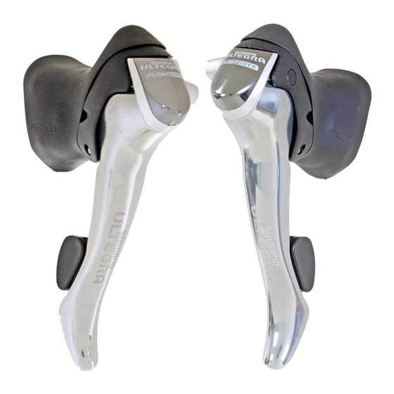
ST-6510
ST-5500-CA
ST-5510
ST-R600
General Safety Information
WARNING
• Obtain, read and carefully service instructions when installing
parts. A loose, worn, or damaged parts may cause injury to
the rider.
We strongly recommend that only genuine Shimano
replacement parts be used.
• Read these Technical Service Instructions carefully, and keep
them in a safe place for later reference.
Note
• Operation of the levers related to gear shifting should be made
only when the front chainwheel is turning.
• For smooth operation, always be sure to use the specified
outer casing and the bottom bracket cable guide.
• Grease the inner cable and the inside of the outer casing
before use to ensure that they slide properly.
• Because the high cable resistance of a frame with internal
cable routing would impair the SIS function, this type of frame
should not be used.
• The end of the outer casing which has the aluminum
cap should be at the derailleur side.
Derailleur side
Aluminum cap
• The cycle computers shown in the table below are compatible.
Meter unit
SC-6500 / SC-6501 / SC-M500
Bracket sensor unit
SM-6500
*1
The bracket cover must be replaced.
(
ST-6510 ---> Replace with bracket cover for ST-6501.
ST-5500-CA ---> Replace with ST-5500-C.
• Read the service instructions for the cycle computer also.
• Parts are not guaranteed against natural wear or deterioration
resulting from normal use.
• For maximum performance we highly recommend Shimano
lubricants and maintenance products.
• For any questions regarding methods of installation,
adjustment, maintenance or operation, please contact a
professional bicycle dealer.
SI-6C80D
Shimano
Total Integration
4-mm cap
Plastic cap or 4-mm cap
*1
/ SM-6500-RS / SM-6501
)
In order to realize the best performance, we recommend that
the following combination be used.
Series
Shifting lever
Outer casing
Gears
Front derailleur
Front chainwheel
Bottom bracket
Rear derailleur
Freehub
Cassette sprocket
Chain
Bottom bracket cable guide
Series
Shifting lever
ST-5500-CA / ST-5510 / ST-R600
Outer casing
Gears
Front derailleur
FD-5500 / FD-5501
Front chainwheel
FC-5501 / FC-5502
Bottom bracket
Rear derailleur
Freehub
Cassette sprocket
Chain
Bottom bracket cable guide
ULTEGRA
ST-6510 / ST-R600
SP40
18
27
FD-6500
FD-6503
FC-6500
FC-6503
BB-6500
RD-6500
RD-6500-GS
FH-6500
CS-6500
CN-HG93 / CN-7701
SM-SP17
SHIMANO 105
SP40
18
27
FD-5503 / FD-5504
FC-5504 / FC-5505
BB-5500
RD-5500 /
RD-5500-GS /
RD-5501
RD-5501-GS
FH-5500 / FH-5501
CS-HG70-9
CN-HG73
SM-SP17
t
Advertisement
Table of Contents


Need help?
Do you have a question about the ST-6510 and is the answer not in the manual?
Questions and answers