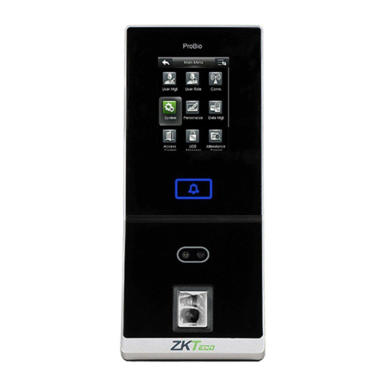
ZKTeco ProBio Installation Manual
Hide thumbs
Also See for ProBio:
- Quick start manual (17 pages) ,
- Quick start manual (17 pages) ,
- User manual (67 pages)
Summary of Contents for ZKTeco ProBio
- Page 1 Safety Precautions INSTALLATION GUIDE ProBio Version: 1.1 Date: September 2021 ProBio Installation Guide...
-
Page 2: Safety Precautions
Do not use the device for any purpose other than those specified. Clean the device often to remove dust on it. While cleaning, do not splash water on the device but wipe it out with smooth cloth or towel. Contact your supplier in case of any problem! ProBio Installation Guide... -
Page 3: Device Overview
Not all products have a fingerprint or card function. The real product shall prevail. ProBio Front View Left Side View ProBio Touch Screen USB Slot Door Bell Reset Button Camera Fingerprint Reader & Card Reader Area ProBio Installation Guide... - Page 4 Device Overview Both ProBio devices have the same pin diagram which is provided below. Power Out Wiegand In 7 Pin Cable Connectors Beep 8 Pin Cable Connectors Wiegand Out RS485 RS232 Tamper Alarm Button 2 Pin Cable Connectors Power 4 Pin Cable Connectors...
-
Page 5: Product Dimensions & Installation
Fix the back plate onto the wall the wall, and drill holes according to the using wall mounting screws. mounting paper. Use security screws to fasten Insert the device into back plate. the device to back plate. ProBio Installation Guide... -
Page 6: Power Connection
12V DC Adaptor With UPS (Optional) 12V DC Recommended Power Supply 12V±10%, at least 500mA (12V /3A is standard). To share the power with other devices, use a power supply with higher current ratings. ProBio Installation Guide... -
Page 7: Ethernet Connection
Ethernet Connection LAN Connection Ethernet Cable Network Cable Adapter Note: The device can be directly connected to PC by using Ethernet cable. ProBio Installation Guide... -
Page 8: Direct Connection
Direct Connection Direct Connection Ethernet Cable Network Cable Adapter ProBio Installation Guide... - Page 9 If RS485 fingerprint reader is powered from the terminal, the length of wire should be less than 100 meters or 330 ft. If the cable length is more than 200 meters or 600 ft., the number 6 switch should be ON ProBio Installation Guide...
-
Page 10: Lock Relay Connection
LOCK (normally closed at power ON) is connected with 'NC1'and 'COM1' terminals. 2. When electrical lock is connected to the Access Control System, you must parallel one FR107 diode (equipped in the package) to prevent the self-inductance EMF from affecting the system. Do not reverse the polarities. ProBio Installation Guide... - Page 11 Lock Relay Connection Device Sharing Power with the Lock 12V DC COM1 Sensor FR107 Diode Normally Closed Lock ProBio Installation Guide...
-
Page 12: Wiegand Output Connection
Wiegand Output Connection Wiegand output connection of ProBio devices is shown below: ProBio Installation Guide... -
Page 13: Standalone Installation
Standalone Installation The standalone installation of ProBio device is shown below: Ethernet ProBio Door Sensor Exit Button Lock Doorbell RS485 Fingerprint Reader ProBio Installation Guide... - Page 14 Third-Party Controller Wiegand Output Connection ProBio ProBio ProBio ProBio ProBio Installation Guide...
-
Page 15: How Does It Work
How Does It Work? The working principle of ProBio device is shown below: ProBio Installation Guide... - Page 16 How to Place a Finger on the Sensor? Note: ZKTeco’s fingerprint readers will give optimal results for fingerprint matching, if the following recommendations and suggestions are followed. Select a finger to enroll It is recommended to use an index finger or a middle finger.
-
Page 17: Troubleshooting
Tips for different fingerprint conditions ZKTeco’s fingerprint products are designed to verify fingerprints with the highest security irrespective of the skin conditions of finger. However, in case a fingerprint cannot be read on the sensor, please refer to the followings tips: ... - Page 18 The Tamper Alarm rings? To cancel the triggered alarm mode, carefully check whether the device and back plate are securely connected to each other, and reinstall the device properly if necessary ProBio Installation Guide...
- Page 19 ZKTeco Industrial Park, No.32, Industrial Road, Tangxia Town, Dongguan, China Tel: +86 769-82109991 Fax: +86 755-89602394 www.zkteco.com Copyright©2021 ZKTECO CO., LTD. All rights reserved. ProBio Installation Guide...


Need help?
Do you have a question about the ProBio and is the answer not in the manual?
Questions and answers