ZKTeco ProBio Quick Start Manual
Hide thumbs
Also See for ProBio:
- Quick start manual (17 pages) ,
- User manual (67 pages) ,
- Installation manual (20 pages)
Table of Contents
Advertisement
Quick Links
Advertisement
Table of Contents

Related Manuals for ZKTeco ProBio


Summary of Contents for ZKTeco ProBio
- Page 1 QUICK START GUIDE ProBio(QR) Version: 1.0 Date: May 2021...
-
Page 2: Safety Precautions
Safety Precautions Before installation, please read the following precautions carefully to prevent risks and dangers to this product, users and surroundings. Do not expose to direct sunlight, water, dust and soot. Do not place magnetic object near the product. Magnetic objects such as Magnet, CRT TV , Monitor or Speaker may damage the device. -
Page 3: User Registration
User Registration 1) Recommended Standing Position For user heights between 1.5m to 1.8m, it is recommended to install the device at 1.15m height above ground (can be modified according to the user’s average height). 0.5m Recommended Procedures (as shown in the left image): During registration and verification procedures, the position of device should not be changed to... -
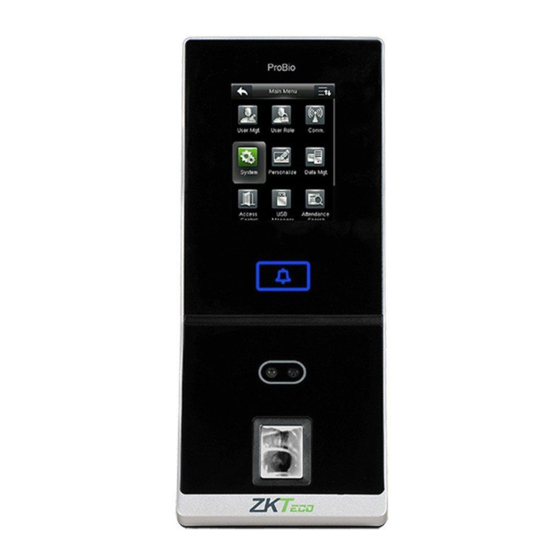
Page 4: Device Overview
Device Overview 2.8" Touch Screen Tamper Switch 190.8mm (7.51") Doorbell Terminal Block Camera Card Reading Area & QR Code Scanner 85mm (3.35") Speaker USB Port Reset Button 103mm (4.05") -
Page 5: Device Installation
Device Installation Installation on the wall ① Attach the mounting template sticker to the wall, and drill holes according to the mounting paper. ② Fix the back plate on the wall using the wall mounting screws. ③ Attach the device to the back plate. ④... -
Page 6: Power Connection
Power Connection Without UPS Auxiliary Power +12V Wiegand BELL- Wiegand IWD0 Bell BELL+ IWD1 Red LED RLED RS232 Sensor Green GLED Button Beep BEEP 485A RS485 485B Lock COM1 RJ45-1 RJ45-2 Ethernet RJ45-3 +12V Alarm Power In RJ45-6 12V DC 12V DC With (Optional) -
Page 7: Ethernet Connection
Ethernet Connection LAN Connection Connect the device and the software over an Ethernet cable. An example is shown below: Auxiliary Power +12V Wiegand BELL- Wiegand IWD0 Bell BELL+ IWD1 Red LED RLED RS232 Sensor Green GLED Button Beep BEEP 485A RS485 485B Lock... - Page 8 RS485 Connection Rs485 Slave Reader Connection DESCRIPTION WIRE + 2V Black IWD0 White IWD1 Green RLED Blue GLED Gray BEEP Purple Auxiliary +12V Power Wiegand BELL- Wiegand IWD0 Bell BELL+ IWD1 Red LED RLED Rs232 Sensor Green GLED Button Beep BEEP 485A RS485...
-
Page 9: Lock Relay Connection
Lock Relay Connection The system supports both Normally Opened Lock Normally Closed Lock . The NO Lock (Normally Opened when powered) is connected with ' ' and ' ' terminals, and the NC Lock (Normally Closed when powered) is connected with ' ' and ' ' terminals. - Page 10 Lock Relay Connection Device Sharing Power with the Lock 12V DC COM1 Auxiliary +12V Power Wiegand BELL- IWD0 Bell Wiegand BELL+ IWD1 Red LED RLED RS232 Sensor Green GLED Button Beep BEEP 485A RS485 485B Lock COM1 RJ45-1 RJ45-2 Ethernet RJ45-3 +12V Alarm...
-
Page 11: Standalone Installation
Standalone Installation ZKBioSecurity ZKBioSecurity Ethernet Input Output ALARM ProBio Emergency Button Alarm Door Sensor No Touch EXIT Exit Button Output Doorbell RS485/ Wiegand USB Disk Card Reader Dynamic QR code Download App Store Google play... -
Page 12: Wiegand Output Connection
Wiegand Output Connection +12V Auxiliary Power Wiegand BELL- IWD0 Wiegand Bell BELL+ IWD1 Red LED RLED Rs232 Sensor Green GLED Button Beep BEEP 485A RS485 485B Lock COM1 RJ45-1 RJ45-2 Ethernet RJ45-3 +12V Alarm Power In RJ45-6 WIRE DESCRIPTION Green White Black Gray... -
Page 13: Device Operation
Gateway Address Serial Number Device Type Set Server Operations Step 3 192.168.163.201 255.255.255.0 192.168.163 201 CJHC203336 ProBio Device Name 192.168.163.201 Icon Type Door Area Area Name Add to Level Clear Data in the Device when Adding The current systen communication port is 6609, please make sure the device is set correctly. - Page 14 Device Operation 2. Click [Add] in the operation column, a new window will pop-up. Select the Icon type, Area, and Add to Level from each drop-down and click [OK] to add the device. 3. Click [Personnel] > [Person] > [New] and fill in all the required fields to register a new user in the software.
- Page 15 Device Operation QR Code as the Mobile Credential The device can recognize the QR code image on the ZKBioSecurity Mobile APP captured by the QR code scanner, making it easy to access without contact. Please set the IP Address and Cloud Service Server Address in the COMM.
- Page 16 ZKTeco Industrial Park, No.32, Industrial Road, Tangxia Town, Dongguan, China. Tel: +86 769-82109991 Fax: +86 755-89602394 www.zkteco.com Copyright©2021 ZKTECO CO., LTD. All rights reserved.
Need help?
Do you have a question about the ProBio and is the answer not in the manual?
Questions and answers