ZKTeco ProBio Quick Start Manual
Hide thumbs
Also See for ProBio:
- Quick start manual (17 pages) ,
- User manual (67 pages) ,
- Installation manual (20 pages)
Table of Contents
Advertisement
Quick Links
Advertisement
Table of Contents

Related Manuals for ZKTeco ProBio


Summary of Contents for ZKTeco ProBio
- Page 1 QUICK START GUIDE ProBio Version: 1.2 Date: September 2021...
-
Page 2: Safety Precautions
Safety Precautions Before installation, please read the following safety precautions for user safety and to prevent product damage. Do not install the device in a place subject to direct sun light, humidity, dust or soot. Do not place a magnet near the product. Magnetic objects such as magnet, CRT, TV, monitor or speaker may damage the device. - Page 3 Cautions on Using Face Recognition Device 1) Recommended Standing Position For user heights between 1.5m to 1.8m, it is recommended to install the device at 1.15m above ground (may be modified according to user average height). a. Recommended Registration and Verification Position Recommended Procedures (as shown in the left image): During registration and verification procedures, the...
-
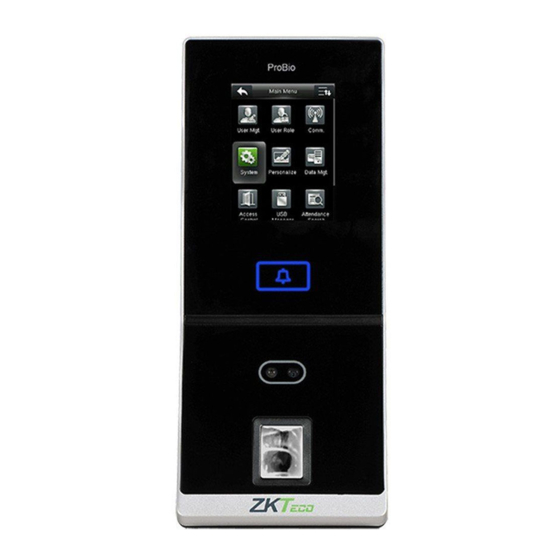
Page 4: Device Overview
During verification, it is required to show your face in the center of the screen and fit your face into the green frame in the screen. Device Overview Not all products have fingerprint or card function, the real product shall prevail. ProBio Front Left Side Touch Screen Doorbell... -
Page 5: Product Dimensions & Installation
Product Dimensions & Installation Product Dimensions 5.08 in 7.51 in (190.8 mm) (129 mm) 4.05 in 2.4 in (103 mm) 3.35 in (61 mm) (85 mm) Mounting the Device on Wall Put the mounting template sticker onto the wall, and drill holes according to the mounting paper. -
Page 6: Power Connection
Power Connection Without UPS 12V DC 12V DC Adaptor With UPS (Optional) 12V DC 12V DC Adaptor Recommended Power Supply 12V±10%, at least 500mA (12V /3A is standard). To share the power with other devices, use a power supply with higher current ratings. -
Page 7: Ethernet Connection
Ethernet Connection LAN Connection Ethernet Cable Network Cable Adaptor Note: The device can be connected to PC directly by Ethernet cable. - Page 8 RS485 Connection RS485 Fingerprint Reader Connection RS485 Fingerprint Reader DIP Settings 1. There are six DIP switches on the back of RS485 fingerprint reader, switches 1-4 are for RS485 address, switch 5 is reserved, switch 6 is for reducing noise on long RS485 cable.
-
Page 9: Lock Relay Connection
Lock Relay Connection Device Not Sharing Power with the Lock COM1 12V DC 12V DC Adaptor Sensor FR107 Diode Normally Closed Lock Notes: 1. The system supports NO LOCK and NC LOCK. For example the NO LOCK (normally opened at power on) is connected with 'NO1' and 'COM1' terminals, and the NC LOCK (normally closed at power on) is connected with 'NC1'and 'COM1' terminals. - Page 10 Lock Relay Connection Device Sharing Power with the Lock 12V DC COM1 Sensor FR107 Diode Normally Closed Lock...
-
Page 11: Wiegand Output Connection
Wiegand Output Connection... -
Page 12: Standalone Installation
Standalone Installation Ethernet Door Sensor Exit Button Lock Doorbell RS485 Fingerprint Reader... -
Page 13: Device Operation
Device Operation Date / Time Settings Press icon to enter the main menu > System > Date Time to set date and time. Adding User Press icon to enter the main menu > User Mgt. > New User to enter the adding New User interface. Settings include inputting user ID, user name, choosing user role (Super Admin / Normal User), registering fingerprint / face / badge number... - Page 14 Device Operation ADMS Settings Press icon to enter the main menu > Comm. > ADMS, to set the parameters which are used for connecting with the ADMS server. When the Webserver is connected successfully, the initial interface will display the logo.
- Page 15 Device Operation Holidays: To set dates of holiday and the access control time zone for that holiday. Combined Verification: To set access control combinations. A combination consists of a maximum of 5 access control groups. Anti-Passback Setup: To prevent passing back which causes risks to security. Once this function is enabled, entry and exit records must be matched in order to open door.
- Page 16 ZKTeco Industrial Park, No.32, Industrial Road, Tangxia Town, Dongguan, China Tel: +86 769-82109991 Fax: +86 755-89602394 www.zkteco.com Copyright©2021 ZKTECO CO., LTD. All rights reserved.
Need help?
Do you have a question about the ProBio and is the answer not in the manual?
Questions and answers