Advertisement
Quick Links
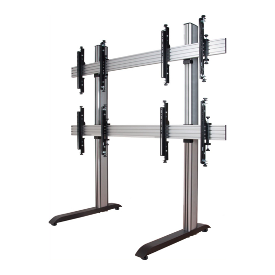
BT8370
UNIVERSAL
VIDEOWALL STAND
INSTALLATION GUIDE
SPECIFICATIONS
• Recommended screen size: 32"- 70"
• Max weight per screen: 50kg (110lbs)
• Suitable for landscape or portrait mounting
• Safety screws help prevent unauthorised removal of screens
• Integrated cable management
• All mounting hardware included
Note: This assembly manual covers di erent installations. Some
parts or procedures shown may not be required for installation.
Please refer to
page 5 for
VESA® xings
www.btechavmounts.com
PER SCREEN
TM
Advertisement

Related Manuals for B-Tech System X BT8370-3X3-BB


Summary of Contents for B-Tech System X BT8370-3X3-BB
- Page 1 BT8370 UNIVERSAL VIDEOWALL STAND INSTALLATION GUIDE SPECIFICATIONS • Recommended screen size: 32”- 70" • Max weight per screen: 50kg (110lbs) • Suitable for landscape or portrait mounting • Safety screws help prevent unauthorised removal of screens • Integrated cable management •...
- Page 2 It is recommended that periodic inspections of the product and its xing points are made as frequently as possible (no more than 6 months apart) to ensure that safety is maintained. B-Tech AV Mounts recommends that a suitably quali ed person is used for the removal of this product.
- Page 3 B-Tech AV Mounts recommends that a professional audio video installer or other suitably quali ed person install this product. B-Tech AV Mounts, its distributors and dealers are not responsible for or responsible for any damage or injury caused by improper installation. This product must be mounted on a suitable structure and it should only be used supporting the maximum weight indicated.
- Page 4 BT8370 PARTS LIST Due to the multiple installations available the quantity for each option below is dependent on the mount ordered. All these components can be moved or carried by manpower. Please be careful to avoid injury when PLEASE KEEP THIS FOR FUTURE REFERENCE handling these components before &...
- Page 5 SPACER INSTALLATION TOOLS REQUIRED BT8390-SP Crosshead PART NAME ITEM 10mm Spanner screwdriver PER PACK SPACER OPTIONAL RAIL EXTENSION KIT BT8390-EXT Knife Level ITEM PART NAME JOINING BAR M6 x 8mm GRUB SCREW 3AF HEX KEY SCREEN INTERFACE KIT Interface Arms Fixed Tilt Micro-Adjustment...
- Page 6 typical installation 2 x 2 Videowall installation with VESA 400 Micro-Adjustment arms INSTALLATION TOOLS REQUIRED Crosshead screwdriver Spanner Knife/Cutter Level (Optional) INSTALLATION notes FLOORSTAND STABILITY • Install stand on level ground • Two person assembly When verifying the stability of the structure, consider the following external factors: 1.
- Page 7 Max load per vertical column: 150kg INSTALLING COLUMNS WITH A HEIGHT OVER 2.4M B-Tech recommends when extending the vertical columns over 2.4m to x item B1 to item A1, connect columns with item D1 and build up, rather than building the product layed down on the oor (as shown in the assembly instructions).
- Page 8 OPTIONAL EXTENDING THE COLUMNS EXTEND VERTICAL COLUMNS i. Insert item B7 halfway into the non-threaded end of item B1. The two joining bars with item B8 go in the front of the column and the 2 joining bars with item B9 go in the back. IMPORTANT: Joining bars should be inserted into the non-threaded end of...
- Page 9 OPTIONAL EXTENDING THE MOUNTING RAIL Combine Mounting Rails together using the BT8390-EXT i. On the intended front facing side of item D1 insert 4 x item F1 half-way into each slot, on the back side insert 1 x item F1 into the top slot and 1 x item F1 into the third slot ( see g.
- Page 10 INSTALLATION INSTRUCTIONS ATTACH JOINING PLATES TO COLUMNS i. On item C1, assemble 4x item C3 to item C2. ii. Lay the column on the oor and t item C1 to item B1. IMPORTANT: Make sure the end with M8 threads are at the bottom of the columns.
- Page 11 iii. Use item E1 to set the distance between items C1 on item B1 according to the screen size. Once set, tighten item C3. ADJUSTMENT KNOB Leave at least a 5mm gap at top of column for item B2.
- Page 12 INSERT SLIDING NUTS INTO MOUNTING RAILS Lay the rail on the oor and for each item C1 used, insert 4x item C2 into item D1. Two in the 2nd channel and two in the bottom channel.
- Page 13 ATTACH COLUMNS TO RAILS On the oor, place item B1 onto item D1. Attach item C1 to item D1 by fastening item C3 into the inserted items C2. Note: To ensure straight assembly of item B1 make sure the distance of items C1 to the end of item D1 are set the same on each rail.
- Page 14 ASSEMBLE BASES TO COLUMNS Attach item A1 to item B1 using items A3 & A4. Once bases are xed to columns, return stand to upright position. THREADED Note: If necessary use item A5 to adjust item...
- Page 15 ATTACH INTERFACE ARMS TO SCREEN Fix items G1 & G2 to the rear of the screen using items A-M. Note: Ensure the arms are A. FIXED ARMS facing the correct way round and the same holes are used on both arms. SCREEN FIXING KIT SCREEN...
- Page 16 (BT8390-VESA400MAF) C. MICRO-ADJUSTMENT ARMS Attach items G1 & G2 to the back of the screens using items A-F. Note: Ensure the arms are SCREEN FIXING KIT facing the correct way round and the same holes are used on both arms. Note: Use spacers for screens with recessed xings SCREEN SCREEN...
- Page 17 (BT8390-VESA400MAP) D. POP-OUT MICRO-ADJUSTMENT ARMS Note: Ensure the arms are i. Attach items G1 & G2 to the back of the screen using items D-I. facing the correct way round and the same holes are used on both arms. SCREEN FIXING KIT SCREEN ii.
- Page 18 MOUNT SCREEN TO RAIL i. Hook the rst screen onto bottom rail of the stand. ii. With a level, align the screen to the oor using the height A & B FIXED & TILT ARMS adjustment screws / knobs on top of the interface arms. HEIGHT ADJUSTMENT SCREW...
- Page 19 iii. Laterally adjust screen by hand. 3 x 3 Video wall installation example Lateral adjustment X axis Lateral Adjustment X axis Note: If mounting 3 or more screens across, mount the rst screen centrally onto the bottom rail. HOOK ON THE REMAINING SCREENS After mounting each screen use the Y &...
- Page 20 Using a level, align the screen to the oor using the Y axis adjustment knobs. Use the Z axis knobs to ensure the screen is perpendicular with the oor. HEIGHT ADJUSTMENT Y AXIS KNOB DEPTH ADJUSTMENT Z AXIS KNOB DEPTH ADJUSTMENT Z AXIS KNOB Lateral Adjustment...
- Page 21 SECURE SCREENS Once screens are aligned, tighten the safety screws on the bottom of items G1 & G2. SAFETY SAFETY SCREW SCREW SERVICING SCREENS (POP-OUT ARMS ONLY) Items G1 & G2 Push centrally at the left and right of the screen popped-out to pop-out the mount.
- Page 22 ADD END CAPS AND COVERS i. After screen cables are connected and routed down the back of item B1, partially clip on the cable management item B3, this allows easy removal if more cables need adding. Once satis ed all cables are tted, clip the covers on fully. ii.
- Page 23 BT8370 DIMENSIONS Depending on installation requirements, the BT8370 Videowall Stand will feature a selection of the following products. PLEASE KEEP THIS FOR FUTURE REFERENCE INTERFACE ARMS BASE BT8380-BASE BT8390-VESA200F BT8390-VESA200T BT8390-VESA400F BT8390-VESA400T 950mm 222mm 793.5mm 86mm 28mm 45.2mm 28mm 45.2mm INTERFACE ARMS BT8390-VESA400MAF BT8390-VESA400MAP...
- Page 24 B-Tech AV Mounts is a division of B-Tech International Design and Manufacturing Ltd. B-Tech, Better By Design & System X are registered trademarks of B-Tech International Design & Manufacturing Ltd. All other brands and product names are trademarks of their respective owners.
Need help?
Do you have a question about the System X BT8370-3X3-BB and is the answer not in the manual?
Questions and answers