B-Tech System X BT8370 Installation Manual & Parts List
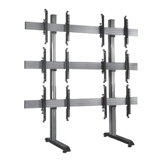
Universal video wall stand
Hide thumbs
Also See for System X BT8370:
- Installation manual & parts list (24 pages) ,
- Installation manual (24 pages)

Related Manuals for B-Tech System X BT8370


Summary of Contents for B-Tech System X BT8370
-
Page 2: Installation Safety Instructions
Please check carefully to make sure there are no missing or defective parts - defective parts must never be used. B-Tech International Limited, its distributors and dealers are not liable or responsible for damage or injury caused by improper installation, improper use or failure to observe these safety instructions. - Page 3 Spole nost B-Tech International Ltd. doporu uje provést instalaci tohoto produktu prost ednictvím odborného instalátora AV i jinak zp sobilé osoby. Spole nost B-Tech International Ltd, její distributo i a prodejci nenesou odpov dnost za škody nebo zran ní zp sobená nevhodnou instalací. Tento výrobek je nutno umístit do vhodné...
- Page 8 Attach Joining Plate to Column cont... ii. Lay column (part B1) on the floor and slide on a joining plate (part C1) for each rail. Note: The number of joining plates per column is dependent on the number of mounting rails being used IMPORTANT: BOTTOM...
- Page 9 iii. Use the spacer (part E1) to set distance between the joining plates (part C1) on the column (part B1) according to the screen size. Once set, tighten all M8 x 16mm screws (part C4) on the joining plate with the hex key (part C5). ADJUSTMENT KNOB Note:...
- Page 10 OPTIONAL: EXTENDING THE MOUNTING RAIL Combine Mounting Rails together using the BT8390-EXT i. On the intended front facing side of the mounting rail (part D1) insert 4 x joining bars (part F1) half-way into each slot, on the back side insert 1 x joining bar into the top slot and 1 x joining bar into the third slot (see fig.
- Page 11 Insert M8 sliding nuts On the back side of each of the mounting rails, insert M8 sliding nuts (part C2) into either end. 2 in the bottom slot and 2 in the second from top slot.
- Page 12 Attach Rails to Columns On the floor, lay the columns (part B1) on the mounting rails (part D1) so the joining plates (part C1) are face down. Through the joining plates, fasten the M8 x 12mm screws (part C3) into the inserted M8 sliding nuts (part C2) attaching the mounting rails to the columns.
- Page 13 Assemble Bases to Columns Attach the bases (part A1) to the columns (part B1) using the support stems (part A2), M8 x 90mm screws (part A3) and washers (part A4). Once bases are fixed, return stand to upright position. IMPORTANT: If mounting a shelf, insert 2 x M8 sliding nuts (part B5) into...
- Page 15 Attach Interface Arms to Screen Attach the interface arms (parts G1) to the back of the screen using the screen fixing kit (parts A-I). SCREEN FIXING KIT A B C D Use spacers for screens with recessed fixings Mount Screen to Rail Hook the first screen onto bottom left of the stand.
Need help?
Do you have a question about the System X BT8370 and is the answer not in the manual?
Questions and answers