Advertisement
Quick Links
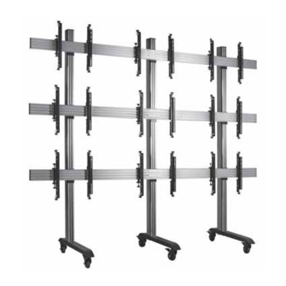
BT8371-3X3
UNIVERSAL MOBILE VIDEO WALL STAND
FOR 3x3 VIDEO WALLS
INSTALLATION GUIDE & PARTS LIST
This Pack Contains 1 Mobile Stand
PLEASE KEEP THIS FOR FUTURE REFERENCE
Installation Safety Notes.....................................................................................................................2
Parts List.............................................................................................................................................6
Installation Instructions...................................................................................................... .................8
Optional Accessories............................................................................................................ ..............18
Product Dimensions..........................................................................................................................19
B-Tech Contact Details........................................................................................................... . ..........20
INSTALLATION TOOLS REQUIRED
Crosshead
screwdriver
B-TECH AUDIO VIDEO MOUNTS
FEATURES
• Designed to mount 9 screens in a 3x3 video wall
formation
• Universal design suitable for all video wall screens
from 46" - 60" (117cm - 152cm)
• Max weight per screen: 50kg
• Designed for screens with VESA & non-VESA
mounting patterns: 200 x 200 up to 600 x 400mm
• Suitable for landscape or portrait screen mounting
• Tool-less micro-adjustments at 8 points for seamless
screen alignment
• Includes non-marking 4" locking/braked castors
and alternative levelling feet
• Stand Dimensions:
W. 3005mm D. 950mm H. 2593mm up to 2793mm
• Collar compatible accessories such as shelves
can be fitted directly to the extrusion
• Integrated cable management
• All mounting hardware included
CONTENTS
Level
www.btechavmounts.com
50kg
PER SCREEN
Knife
TM
Advertisement

Subscribe to Our Youtube Channel
Related Manuals for B-Tech BT8371-3X3


Summary of Contents for B-Tech BT8371-3X3
-
Page 1: Table Of Contents
• Integrated cable management • All mounting hardware included 50kg PER SCREEN CONTENTS Installation Safety Notes........................2 Parts List.............................6 Installation Instructions........................8 Optional Accessories..........................18 Product Dimensions..........................19 B-Tech Contact Details........................20 INSTALLATION TOOLS REQUIRED Crosshead screwdriver Level Knife B-TECH AUDIO VIDEO MOUNTS www.btechavmounts.com... -
Page 2: Installation Safety Notes
Please check carefully to make sure there are no missing or defective parts - defective parts must never be used. B-Tech International Limited, its distributors and dealers are not liable or responsible for damage or injury caused by improper installation, improper use or failure to observe these safety instructions. - Page 3 Spole nost B-Tech International Ltd. doporu uje provést instalaci tohoto produktu prost ednictvím odborného instalátora AV i jinak zp sobilé osoby. Spole nost B-Tech International Ltd, její distributo i a prodejci nenesou odpov dnost za škody nebo zran ní zp sobená nevhodnou instalací. Tento výrobek je nutno umístit do vhodné...
- Page 4 WARNING CAN TIP OVER WHICH MAY LEAD TO SERIOUS INJURY. DO NOT ALLOW CHILDREN UNDER 16 TO MOVE TROLLEY. MOVE TROLLEY SLOWLY ALWAYS APPLY BRAKES WHEN NEVER LEAVE TROLLEY ON TROLLEY IS STATIONARY AN INCLINE. RELEASE BRAKES WHEN PUSHING ALWAYS PARK ON LEVEL GROUND TROLLEY.
- Page 5 INSTALLATION NOTES • Min. Two person assembly • Approx. minimum floor space required for assembly: 5m • Floor fixing kit available BT8380-FBK - see page 18 FLOORSTAND STABILITY • Install mobile stand on level ground When verifying the stability of the structure, consider the following external factors: 1.
-
Page 6: Parts List
BT8371-3X3 PARTS LIST SPACER MOUNTING RAIL BT8390-150 (x6) BT8390-SP (x1) EXTENSION BARS BT8390-EXT (x3) COLUMN BT8380-240 (x3) JOINING PLATE BT8380-JPK (x9) Optional - To fix shelves to a vertical column BASE BT8380-BASE (x3) - Page 7 BASE BT7564 (x9) ADAPTOR ARMS TOTAL PART NAME BASE For use with 55" screens with 600 x 400mm VESA fixings SUPPORT STEM M8 x 90mm SCREW M8 WASHER LEVELLING FOOT 6AF HEX KEY 24mm SPANNER CASTORS INTERFACE ARMS TOTAL PART NAME BT8390-VESA400MAF (x9) CASTOR COLUMN...
-
Page 8: Installation Instructions
INSTALLATION INSTRUCTIONS Attach the Joining Plate to the Vertical Column i. Connect together four M8 x 16mm screws (part D4) with M8 sliding nuts (part D2) on each joining plate (part D1). ii. Lay column (part C1) on the floor and slide three joining plates (part D1) onto each column. - Page 9 iii. Use the spacer (part G1) to set distance between the each joining plate (part D1) on the column (part C1) according to the screen size. Once set, tighten all M8 x 16mm screws (part D4) on joining plate with hex key (part D5). ADJUSTMENT KNOB Leave at least...
- Page 10 Combine 2 mounting rails together using the BT8390-EXT i. On the intended front facing side of the mounting rail (part E1) insert 4 x joining bars (part F1) half-way into each slot, on the back side insert 1 joining bar into the top slot and 1 bar into the third slot.
- Page 11 Attach columns to mounting rails On the floor, lay the vertical columns (part C1) equal distance apart on the mounting rails (part E1) so the joining plates are face down. Attach the mounting rails (part E1) to the columns (part C1) using the joining plates (part D1), fastening M8 x 12mm screws (part D3) into the inserted M8 sliding nuts (part D2).
- Page 12 Assemble Bases to Columns i. If required, unscrew the levelling feet (part A5) on the base (part A1) and replace with the castors (part B1) before attaching bases to the columns. Ensure castors are set on the braked position for assembly. ii.
- Page 13 Attach Interface Arms to Screen Attach the interface arms (parts H1 and H2) to the back of the screen using the screen fixing kit (parts A-F). INTERFACE ARM LEFT A B C INTERFACE ARM RIGHT Use spacers for screens with Use adaptor arms (part I1) for 55”...
- Page 14 Hook the screens onto the stand i. Hook the first screen centrally onto the bottom rail and align screen with the horizontal centre of the trolley / stand ii. Using a level, align the flat screen to the floor using the Z axis adjustment knobs. iii.
- Page 15 Lateral Adjustment X axis iv. Hook on the remaining flat screens.
- Page 16 Align and secure screens i. Use the Y & Z micro-adjustment knobs on interface arms to align screens. ii. When the screens are all positioned correctly, tighten the safety screws on the bottom of each interface arm (parts H1 & H2) to secure to stand. Y AXIS ADJUSTMENT KNOB Total Z axis...
- Page 17 Add End Caps and Cable Management Covers i. After screen cables are connected, slide the cable management covers (part C3) down the rear of columns (part C1). ii. Fit end caps (parts C4 & E2) to the columns and mounting rails (parts C1 & E1). iii.
-
Page 18: Optional Accessories
AV Component Shelfs the vertical column (part C1) front slots before attaching base to column. Mount a B-Tech Shelf (BT7032 / BT7172 / BT7172 / BT7173) by fastening the M8 x 16mm screws (part C6) to the M8 sliding nuts. -
Page 19: Product Dimensions
BT8371-3X3 PRODUCT DIMENSIONS 3005mm 1500mm 1500mm 404mm 1000 - 1300mm 55.5mm 136.1mm 950mm THESE INSTRUCTIONS ARE INTENDED AS A GUIDE ONLY AND B-TECH ACCEPTS NO LIABILITY FOR THE ACCURACY OF THE INFORMATION CONTAINED IN THIS DOCUMENT. -
Page 20: B-Tech Contact Details
©2015 B-Tech International Limited. All rights reserved. B-Tech Audio Video Mounts is a division of B-Tech International Limited. B-Tech, Better By Design & System X are registered trademarks of B-Tech International Limited. All other brands and product names are trademarks of their respective owners.
Need help?
Do you have a question about the BT8371-3X3 and is the answer not in the manual?
Questions and answers