Advertisement
Quick Links
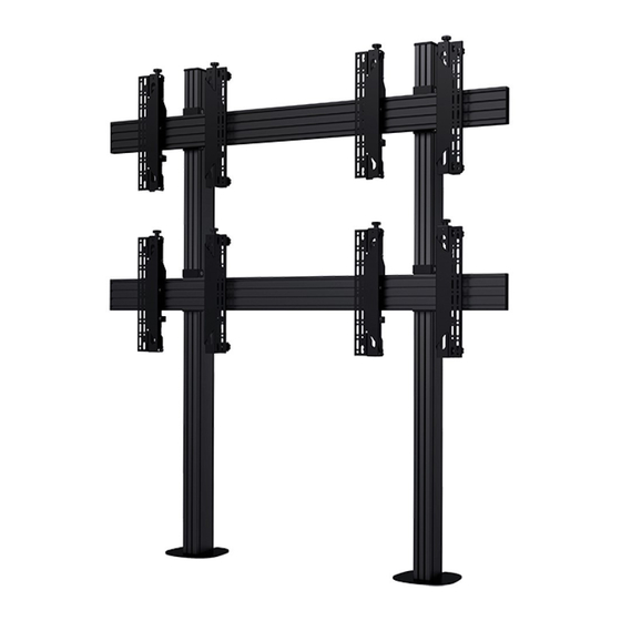
BT8372
UNIVERSAL BOLT DOWN VIDEOWALL STAND
INSTALLATION GUIDE & PARTS LIST
This Pack Contains 1 Stand
PLEASE KEEP THIS FOR FUTURE REFERENCE
Installation Safety Notes......................................................................................................................2
Parts List.............................................................................................................................................4
Installation Notes.................................................................................................................................6
Installation Instructions......................................................................................................................10
B-Tech Contact Details........................................................................................................... . ..........24
INSTALLATION TOOLS REQUIRED
Crosshead
screwdriver
CONTENTS
Spanner
or Socket
Floor fixings not supplied
B-TECH AV MOUNTS
www.btechavmounts.com
FEATURES
• Universal stand suitable for video wall screens
from 32" - 70" (81cm - 177cm)
• Max weight per screen: 50kg (110lbs)
• Designed for screens with VESA & non-VESA
mounting patterns
• Suitable for landscape or portrait screen mounting
• Collar compatible accessories such as shelves
can be fitted directly to the extrusion
• Integrated cable management
This assembly manual covers different installations.
Please note that some parts or procedures shown
may not be required for installation.
Drill
Pencil
50kg
PER SCREEN
Level
Knife
TM
Advertisement

Related Manuals for B-Tech BT8372


Summary of Contents for B-Tech BT8372
-
Page 1: Table Of Contents
Please note that some parts or procedures shown may not be required for installation. 50kg PER SCREEN CONTENTS Installation Safety Notes........................2 Parts List.............................4 Installation Notes..........................6 Installation Instructions........................10 B-Tech Contact Details........................24 INSTALLATION TOOLS REQUIRED Crosshead Spanner Drill Pencil Level Knife screwdriver... -
Page 4: Parts List
BT8372 Due to the multiple installations available each option below PARTS LIST is dependent on the stand ordered. PLEASE KEEP THIS FOR FUTURE REFERENCE BASE BT8380-FFB PART NAME PER PACK BASE M8 x 35mm SCREW 5AF HEX KEY COLUMN Optional... - Page 5 SPACER BT8390-SP PART NAME ITEM PER PACK SPACER OPTIONAL RAIL EXTENSION KIT BT8390-EXT PART NAME ITEM TOTAL PER PACK JOINING BAR M6 x 8mm GRUB SCREW 3AF HEX KEY Screen Interface Arms INTERFACE KIT BT8390-VESA200F BT8390-VESA400F BT8390-VESA400MAF PART NAME ITEM PER PACK SCREEN INTERFACE ARM M6 x 8mm HEX SCREW...
-
Page 6: Installation Notes
2. Exposure to sudden and severe wind. 3. Danger arising from contact with people and / or objects. (eg installations in passageways, emergency exits). BT8372 MAX LOAD CONFIGURATIONS MAX COLUMN HEIGHT 4.2M Note: Screen weight must be evenly spread up the vertical column SINGLE COLUMN INSTALLATIONS Column height: Up to 1.8m... - Page 7 Installing columns with a height over 2.4M B-Tech recommends when extending the vertical columns over 2.4m to fix the first two columns (item B1) to the bases (item A1) and connect with a horizontal rail (item D1) and bolt to the floor, then build up, rather than building the product layed down on the floor (as shown in the assembly instructions).
- Page 8 OPTIONAL: EXTENDING THE COLUMNS i. Insert the joining bars (item B7) halfway into the non-threaded end of the column (item B1). The two joining bars with grub screws (item B8) go in the front of the column and the 2 joining bars with hex bolts (item 9) go in the back.
- Page 9 OPTIONAL: EXTENDING THE MOUNTING RAIL Combine Mounting Rails together using the BT8390-EXT i. On the intended front facing side of the mounting rail (item D1) insert 4 x joining bars (item F1) half-way into each slot, on the back side insert 1 x joining bar into the top slot and 1 x joining bar into the third slot (see fig.
-
Page 10: Installation Instructions
INSTALLATION INSTRUCTIONS Attach Joining Plate to Column i. Connect together the M8 x 12mm (item C3) with M8 Sliding Nut (item C2) onto the joining plates (item C1). ii. Lay columns (items B1) on the floor and slide on the joining plates (item C1). IMPORTANT: Make sure the end with M8 threads are at the bottom of the columns. - Page 11 iii. Use the spacer (item F1) to set the distance between joining plates (items C1) on the column (item B1) according to the screen size. Once set, tighten the M8 x 12mm screws (item C3). ADJUSTMENT KNOB Leave at least a 5mm gap at the top of the column (item B1) for the end cap (item B2)
- Page 12 Insert Sliding Nuts into Mounting Rails Lay mounting rails (item D1) on the floor and insert 4 x M8 sliding nuts (item D2). 2 in the second slot, 2 in the bottom slot. Insert 4 sliding nuts for each joining plate (item D1) to be attached to the rail.
- Page 13 Attach Rails to Columns On the floor, lay the columns (item B1) face down onto the mounting rails (item D1). Through the joining plates (item D1), fasten the M8 x 12mm screws (item C3) into the M8 sliding nuts (item C2) attaching the mounting rails to the columns. To ensure straight assembly of columns (item B1), make sure the distance of the outer joining plates (item C1) to the end of the rails (item D1) are set the same on each rail.
- Page 14 item item item...
- Page 15 Bolt stand to the floor Pre-drill holes in floor and using suitable ground anchor fixings (not supplied), fix stand to floor. 86mm 10.5mm 165mm GROUND ANCHOR CONCRETE FLOOR...
- Page 16 Attaching Fixed and Tilt Interface Arms to the Screens Attach the interface arms (items G1) to the back of the screen using the screen fixing kit (items A-I). Ensure the arms are positioned the correct way round and the same holes are used on both arms.
- Page 17 Attaching Micro-Adjustment Interface Arms to Screen (BT8390-VESA400MAF) Attach the interface arms (items G1) to the back of the screen using the screen fixing kit (items D-I). Ensure the arms are positioned the correct way round and the same holes are used on both arms. INTERFACE ARM LEFT SCREEN FIXING KIT INTERFACE ARM RIGHT...
- Page 18 Attaching Pop-Out Interface Arms to Screens (BT8390-VESA400MAP) i. Attach the interface arms (items G1) to the back of the screen using the screen fixing kit (items D-I). Ensure the arms are positioned the correct way round and the same holes are used on both arms. SCREEN FIXING KIT INTERFACE ARM LEFT INTERFACE ARM RIGHT...
- Page 19 Mount Screen to Rail i. Hook the first screen onto bottom left of the stand. A. FIXED & TILT ARMS B. BT8390-VESA400MAF ARMS C. BT8390-VESA400MAP ARMS ii. With a level, align the screen to the floor using the height A. FIXED & TILT ARMS adjustment screws / knobs on top of the interface arms.
- Page 20 iii. Laterally adjust screen by hand. 3 x 3 Video wall installation example Lateral adjustment X axis Lateral Adjustment X axis NOTE: If mounting 3 or more screens across, mount the first screen centrally onto the bottom rail. Hook on the remaining screens After mounting each screen use the Y &...
- Page 21 Using a level, align the screen to the floor using the Z axis adjustment knobs. Use the Y axis knobs to ensure the screen is perpendicular with the floor. HEIGHT ADJUSTMENT Z AXIS KNOB DEPTH ADJUSTMENT Y AXIS KNOB DEPTH ADJUSTMENT Y AXIS KNOB Lateral Adjustment...
- Page 22 Secure Screens Once screens are aligned, tighten the safety screws on the bottom of interface arms (item G1) SAFETY SAFETY SCREW SCREW Servicing Screens (Pop-Out Arms only) Push centrally at the left and right of the screen Item G1 to pop-out the mount. The screen will rest in the popped-out 'open' position for servicing.
- Page 23 Add End Caps and Cable Management Covers i. After screen cables are connected and routed down the back of the columns (item B1), partially clip on the cable management covers (item B3), this allows easy removal if more cables need adding. Once satisfied all cables are fitted, clip the covers on fully. ii.
-
Page 24: B-Tech Contact Details
B-Tech AV Mounts is a division of B-Tech International Design & Manufacturing Ltd. B-Tech, Better By Design & System X are registered trademarks of B-Tech International Design & Manufacturing Ltd. All other brands and product names are trademarks of their respective owners.
Need help?
Do you have a question about the BT8372 and is the answer not in the manual?
Questions and answers