
Related Manuals for MSA QuickServer FS-QS-1 Series


Summary of Contents for MSA QuickServer FS-QS-1 Series
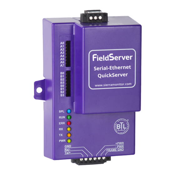
- Page 1 Operating Manual QuickServer FS-QS-1XXX Start-up Guide Revision: 3.L Document No.:T18600 Print Spec: 10000005389 (F) MSAsafety.com...
- Page 2 EMEA Support Information: 1991 Tarob Court +1 408 964-4443 +31 33 808 0590 Milpitas, CA 95035 +1 800 727-4377 Email: smc-support.emea@msasafety.com Email: smc-support@msasafety.com For your local MSA contacts, please go to our website www.MSAsafety.com © MSA 2021. All rights reserved...
-
Page 3: Table Of Contents
Contents About the QuickServer Certification Supplied Equipment Equipment Setup Mounting Physical Dimensions 2.2.1 Dimension Drawing FS-QS-1X10-XXXX 2.2.2 Dimension Drawing FS-QS-1XX1-XXXX R2 Port Jumper Settings 2.3.1 RS-485 Port 2.3.2 M-Bus Port: Master/Slave Jumper R1 Port Small DIP Switches 2.4.1 RS-485 Port Installing the QuickServer RS-485 3.1.1 RS-485 Connection R2 Port... - Page 4 Test and Commission the QuickServer 8.4.1 Accessing the FieldServer Manager MSA Grid - FieldSever Manager Setup Registration Process User Setup Finish Registering the FieldServer Login to the FieldServer Manager Additional Model Connection Ports 10.1 KNX Connection R2 Port 10.2 M-Bus Connection R2 Port Troubleshooting 11.1...
-
Page 5: About The Quickserver
NOTE: For troubleshooting assistance refer to Section Troubleshooting, or any of the troubleshooting appendices in the related driver supplements. Check the MSA Safety website for technical support resources and documentation that may be of assistance. The QuickServer is cloud ready and connects with MSA Safety’s Grid. See Section... -
Page 6: Equipment Setup
If the FieldServer is removed from the DIN rail, use the original screws to reattach. Only screws supplied by MSA Safety should be used in the holes found on the back of the unit when attaching the optional DIN Rail bracket. USE OF ANY OTHER SCREWS MAY DAMAGE THE UNIT. -
Page 7: Physical Dimensions
Physical Dimensions 2.2.1 Dimension Drawing FS-QS-1X10-XXXX QuickServer FS-QS-1XXX Start-up Guide... -
Page 8: Dimension Drawing Fs-Qs-1Xx1-Xxxx
2.2.2 Dimension Drawing FS-QS-1XX1-XXXX QuickServer FS-QS-1XXX Start-up Guide... -
Page 9: R2 Port Jumper Settings
R2 Port Jumper Settings Gently remove the QuickServer enclosure to access the jumpers on the unit. 2.3.1 RS-485 Port NOTE: The following Sections only apply to QuickServer models: FS-QS-1011 and FS-QS-1211. Bias Resistors The QuickServer bias resistors are used to keep the RS-485 bus to a known state, when there is no transmission on the line (bus is idling), to help prevent false bits of data from being detected. - Page 10 Termination Resistor Termination resistors are also used to reduce noise. These pull the two lines of an idle bus together. However, they would override the effect of any bias resistors, if connected. QuickServer FS-QS-1XXX Start-up Guide...
- Page 11 Power Jumper Settings The QuickServer Carrier Board power jumper is set to position A by default but can be changed to position B for other power supply requirements. Position A: The Carrier makes use of a full-wave rectifying bridge. Can be used for 12-24VAC input or 9 –...
-
Page 12: M-Bus Port: Master/Slave Jumper
2.3.2 M-Bus Port: Master/Slave Jumper NOTE: The following only applies to models: FS-QS-1A50, FS-QS-1A51, FS-QS-1B51, FS-QS-1B51, FS-QS-1C51 and FS-QS-1C51. The Master/Slave jumper is used to set the M-Bus hardware as a Master or Slave device (indicated by the labels on the board). -
Page 13: R1 Port Small Dip Switches
R1 Port Small DIP Switches Gently remove the QuickServer enclosure to access the small DIP switches for the R1 Port. 2.4.1 RS-485 Port NOTE: The following only applies to QuickServer models FS-QS-1XX0 or all non-LonWorks models. • If more than one RS-485 device is connected to the network, then the field bias resistor switch needs to be enabled to ensure proper communication. -
Page 14: Installing The Quickserver
Installing the QuickServer RS-485 3.1.1 RS-485 Connection R2 Port Connect to the 3 pins on the left-hand-side of the 6-pin connector as shown. The following Baud Rates are supported on the R2 Port: 4800, 9600, 19200, 38400, 57600, 115200 For details on other types of connection ports, refer to Section 10 Additional Model Connection Ports. -
Page 15: Quickserver Lonworks (Fs-Qs-1Xx1-Xxxx)
QuickServer LonWorks (FS-QS-1XX1-XXXX) Connect the QuickServer to the LonWorks terminal using a twisted pair non-shielded cable. To commission the QuickServer LonWorks port, insert a small screwdriver in the commissioning hole on the face of the QuickServer’s enclosure to access the Service Pin. See the instructions on the QuickServer as to which way to toggle the screwdriver during commissioning. -
Page 16: Rs-232 Connection R2 Port (Only Available On Fs-Qs-122X Models)
RS-232 Connection R2 Port (Only Available on FS-QS-122X Models) Refer to Section 10 Additional Model Connection Ports for further hardware connection options. The following Baud Rates are supported on the R2 Port: 4800, 9600, 19200, 38400, 57600, 115200 QuickServer FS-QS-1XXX Start-up Guide... -
Page 17: Operation
Operation Power Up the Device Apply power to the device. Ensure that the power supply used complies with the specifications provided. Ensure that the cable is grounded using the “Frame GND” terminal. The QuickServer is factory set for 9-30V DC or 12-24V AC. Connect the PC to the QuickServer Over the Ethernet Port •... -
Page 18: Connecting To The Quickserver
Using the FieldServer Toolbox to Discover and Connect to the QuickServer • Install the Toolbox application from the USB drive or download it from the MSA Safety website. • Use the FS Toolbox application to find the QuickServer and connect to the QuickServer. -
Page 19: Setup Web Server Security
Setup Web Server Security Login to the FieldServer The first time the FieldServer GUI is opened in a browser, the IP Address for the gateway will appear as untrusted. This will cause the following pop-up windows to appear. • When the Web Server Security Unconfigured window appears, read the text and choose whether to move forward with HTTPS or HTTP. - Page 20 • Additional text will expand below the warning, click the underlined text to go to the IP Address. In the example below this text is “Proceed to <FieldServer IP> (unsafe)”. • When the login screen appears, put in the Username (default is “admin”) and the Password (found on the label of the FieldServer).
-
Page 21: Select The Security Mode
Select the Security Mode On the first login to the FieldServer, the following screen will appear that allows the user to select which mode the FieldServer should use. NOTE: Cookies are used for authentication. NOTE: To change the web server security mode after initial setup, go to Section 12.1 Change Web Server Security Settings After Initial Setup. -
Page 22: Https With Own Trusted Tls Certificate
6.2.1 HTTPS with Own Trusted TLS Certificate This is the recommended selection and the most secure. Please contact your IT department to find out if you can obtain a TLS certificate from your company before proceeding with the Own Trusted TLS Certificate option. •... -
Page 23: Setup Network
NOTE: The FieldServer Manager tab (see image above) allows users to connect to the Grid, MSA Safety’s device cloud solution for IIoT. The FieldServer Manager enables secure remote connection to field devices through a FieldServer and its local applications for configuration, management, maintenance. -
Page 24: Using Fs-Gui To Input Network Settings
Using FS-GUI to Input Network Settings To navigate from the FS-GUI page to the Network Settings page follow the below instructions: • Find the Navigation tree across the left side of the screen. • Click the arrow next to the FieldServer title/CN number to expand the tree. •... -
Page 25: Routing Settings
Routing Settings The Routing settings make it possible to set up the IP routing rules for the FieldServer’s internet and network connections. • Click the Add Rule button to add a new row and set a new Destination Network, Netmask and Gateway IP Address as needed. -
Page 26: Ethernet 1 Network Settings
Ethernet 1 Network Settings To change the IP Settings, follow these instructions: • Enable DHCP to automatically assign IP Settings or modify the IP Settings manually as needed, via these fields: IP Address, Netmask, Default Gateway, and Domain Name Server1/2. NOTE: If the FieldServer is connected to a router, the IP Gateway of the FieldServer should be set to the same IP Address of the router. -
Page 27: Configuring The Quickserver
Configuring the QuickServer Retrieve the Sample Configuration File The configuration of the QuickServer is provided to the QuickServer’s operating system via a comma-delimited file called “CONFIG.CSV”. If a custom configuration was ordered, the QuickServer will be programmed with the relevant device registers in the Config.csv file for the initial start-up. -
Page 28: Load The Updated Configuration File
Load the Updated Configuration File 8.3.1 Using the FS-GUI to Load a Configuration File • In the main menu of the FS-GUI screen, click “Setup”, then “File Transfer” and finally “Update”. • Browse and select the .csv file, open, then click “Submit”. •... -
Page 29: Retrieve The Configuration File For Modification Or Backup
8.3.2 Retrieve the Configuration File for Modification or Backup To get a copy of the configuration file for modifying or backing up a configuration on a local computer, do the following: • In the main menu of the FS-GUI screen, click “Setup”, then “File Transfer”. •... -
Page 30: Test And Commission The Quickserver
NOTE: For troubleshooting assistance refer to Section Troubleshooting, or any of the troubleshooting appendices in the related driver supplements and configuration manual. MSA Safety also offers a technical support on the MSA Safety website, which contains a significant number of resources and documentation that may be of assistance. -
Page 31: Msa Grid - Fieldsever Manager Setup
MSA Grid - FieldSever Manager Setup The MSA Grid is MSA Safety’s device cloud solution for IIoT. Integration with the MSA Grid - FieldServer Manager enables the a secure remote connection to field devices through a FieldServer and hosts local applications for device configuration, management, as well as maintenance. - Page 32 • To register, fill in the user details, site details, gateway details and account credentials. ◦ Enter user details and click Next ◦ Enter the site details by entering the physical address fields or the latitude and longitude then click Next QuickServer FS-QS-1XXX Start-up Guide...
- Page 33 ◦ Enter Name and Description (required) then click Next ◦ Click the “Create an Grid FieldServer Manager account” button ◦ Enter a valid email and click the Create Account button to send a “Welcome to the MSA Grid” invite to the email address entered...
-
Page 34: User Setup
Process), follow the instructions below to set up login details: • The “Welcome to the MSA Grid - FieldServer Manager” email will appear as shown below. NOTE: If no email was received, check the spam/junk folder for an email from notification@fieldpop.io. Contact the manufacturer’s support team if no email is found. - Page 35 • Click the “Complete Registration” button and fill in user details accordingly. • Fill in the name, phone number, password fields and click the checkbox to agree to the privacy policy and terms of service. NOTE: If access to data logs using RESTful API is needed, do not include “#” in the password. •...
-
Page 36: Finish Registering The Fieldserver
Finish Registering the FieldServer • Enter the new Username and Password set up in Section 9.2 User Setup. QuickServer FS-QS-1XXX Start-up Guide... - Page 37 • Once the device has successfully been registered, a confirmation window will appear. Click the Close button and the following screen will appear listing the device details and additional information auto-populated by the QuickServer. NOTE: Update these details at any time by going to the device’s FS-GUI webpage, clicking the FieldServer Manager button and then clicking the Update Device Details button.
-
Page 38: Login To The Fieldserver Manager
After the gateway is registered, go to www.smccloud.net and type in the appropriate login information as per registration credentials. NOTE: If the login password is lost, see the MSA Grid - FieldServer Manager Start-up Guide for recovery instructions. QuickServer FS-QS-1XXX Start-up Guide... - Page 39 NOTE: For additional FieldServer Manager instructions see the MSA Grid - FieldServer Manager Start-up Guide. QuickServer FS-QS-1XXX Start-up Guide...
-
Page 40: Additional Model Connection Ports
Additional Model Connection Ports 10.1 KNX Connection R2 Port NOTE: The following only applies to models: FS-QS-1240 and FS-QS-1241. The KNX QuickServer is used to transfer data to and from devices using KNX protocol. The KNX driver enables data access from KNX networks to other FieldServer protocols. Most KNX data-point types are supported, allowing communication to almost any kind of KNX device in an installation, such as temperature sensors, shutters, light switches, actuators, alarms, etc. -
Page 41: M-Bus Connection R2 Port
10.2 M-Bus Connection R2 Port NOTE: The following only applies to models: FS-QS-1A50, FS-QS-1A51, FS-QS-1B50, FS-QS-1B51, FS-QS-1C50 and FS-QS-1C51. The M-Bus driver allows the FieldServer to transfer data to and from devices using M-Bus protocol. The Fieldbus connection is included with the FieldServer. The M-Bus QuickServer Gateway is configurable to act as both a Master and a Slave M-Bus device. -
Page 42: Troubleshooting
Troubleshooting 11.1 Communicating with the QuickServer Over the Network • Confirm that the network cabling is correct. • Confirm that the computer network card is operational and correctly configured. • Confirm that there is an Ethernet adapter installed in the PC’s Device Manager List, and that it is configured to run the TCP/IP protocol. -
Page 43: Taking A Fieldserver Diagnostic Capture
11.2 Taking a FieldServer Diagnostic Capture When there is a problem on-site that cannot easily be resolved, perform a Diagnostic Capture before contacting support. Once the Diagnostic Capture is complete, email it to technical support. The Diagnostic Capture will accelerate diagnosis of the problem. •... -
Page 44: Led Functions
11.3 LED Functions Light Description SPL LED will be on when a configured node in the QuickServer is detected as being offline. For details, check the FS-GUI Node overview screen in FS-GUI (click “View” then “Nodes”). For LonWorks units, LED will light until the unit is commissioned on the LonWorks network. RUN LED will flash 20 seconds after power up, signifying normal operation. -
Page 45: Internet Browser Software Support
11.4 Internet Browser Software Support The following web browsers are supported: • Chrome Rev. 57 and higher • Firefox Rev. 35 and higher • Microsoft Edge Rev. 41 and higher • Safari Rev. 3 and higher NOTE: Internet Explorer is no longer supported as recommended by Microsoft. NOTE: Computer and network firewalls must be opened for Port 80 to allow FieldServer GUI to function. -
Page 46: Additional Information
Additional Information 12.1 Change Web Server Security Settings After Initial Setup NOTE: Any changes will require a FieldServer reboot to take effect. • Navigate from the QuickServer landing page to the FS-GUI by clicking the blue “Diagnostics” text on the bottom of the screen. -
Page 47: Change Security Mode
12.1.1Change Security Mode • Click Security in the Navigation panel. • Click the Mode desired. ◦ If HTTPS with own trusted TLS certificate is selected, follow instructions in Section 6.2.1 HTTPS with Own Trusted TLS Certificate • Click the Save button. QuickServer FS-QS-1XXX Start-up Guide... -
Page 48: Edit The Certificate Loaded Onto The Fieldserver
12.1.2Edit the Certificate Loaded onto the FieldServer NOTE: A loaded certificate will only be available if the security mode was previously setup as HTTPS with own trusted TLS certificate. • Click Security in the Navigation panel. • Click the Edit Certificate button to open the certificate and key fields. •... -
Page 49: Change User Management Settings
12.2 Change User Management Settings • From the FS-GUI page, click Setup in the Navigation panel. • Click User Management in the navigation panel. NOTE: If the passwords are lost, the unit can be reset to factory settings to reinstate the default unique password on the label. -
Page 50: Create Users
12.2.1Create Users • Click the Create User button. • Enter the new User fields: Name, Security Group and Password. ◦ User details are hashed and salted NOTE: The password must meet the minimum complexity requirements. An algorithm automatically checks the password entered and notes the level of strength on the top right of the Password text field. •... -
Page 51: Edit Users
12.2.2Edit Users • Click the pencil icon next to the desired user to open the User Edit window. • Once the User Edit window opens, change the User Security Group and Password as needed. • Click Confirm. • Once the Success message appears, click OK. QuickServer FS-QS-1XXX Start-up Guide... -
Page 52: Delete Users
12.2.3Delete Users • Click the trash can icon next to the desired user to delete the entry. • When the warning message appears, click Confirm. QuickServer FS-QS-1XXX Start-up Guide... -
Page 53: Change Fieldserver Password
12.2.4Change FieldServer Password • Click the Password tab. • Change the general login password for the FieldServer as needed. NOTE: The password must meet the minimum complexity requirements. An algorithm automatically checks the password entered and notes the level of strength on the top right of the Password text field. QuickServer FS-QS-1XXX Start-up Guide... -
Page 54: Quickserver Fs-Qs-101X Dcc
12.3 QuickServer FS-QS-101X DCC Driver Code BACnet/IP – BACnet MS/TP 0285 BACnet/IP – LonWorks 0131 JCI Metasys N2 – LonWorks 0097 JCI Metasys N2– BACnet MS/TP 0309 JCI Metasys N2– BACnet/IP 0122 Modbus RTU – BACnet MS/TP 0367 Modbus RTU – BACnet/IP 0104 Modbus RTU –... -
Page 55: Quickserver Part Numbers
12.4 QuickServer Part Numbers Interface Connections QuickServer RS-232 RS-485 M-Bus Ethernet LonWorks FS-QS-1011 FS-QS-1211 FS-QS-1221 FS-QS-1240 FS-QS-1241 FS-QS-1A50 FS-QS-1A51 FS-QS-1B50 FS-QS-1B51 FS-QS-1C50 FS-QS-1C51 TX/Rx/GND +/-/Frame Ground 10/100 Base T FTT10 KNX/EIB TP1 QuickServer FS-QS-1XXX Start-up Guide... -
Page 56: Compliance With Ul Regulations
12.5 Compliance with UL Regulations For UL compliance, the following instructions must be met when operating the QuickServer. • The units shall be powered by listed LPS or Class 2 power supply suited to the expected operating temperature range. • The interconnecting power connector and power cable shall: ◦... -
Page 57: Specifications
12.6 Specifications FS-QS-1011-XXXX/FS-QS-12X1-XXXX/ FS-QS-12X0-XXXX/ FS-QS-1X50-XXXX FS QS-1X51-XXXX 6-pin Phoenix connector: RS-485 or RS-232, +/- ground port, power +/- frame ground port Ethernet-10/100 port Electrical Connections 3-pin RS-485 +/- ground port 2-pin FTT-10 LonWorks port Input Voltage: 9-30VDC or 12-24VAC Input Power Frequency: 50/60 Hz. Power Rating: 2.5 Watts Power Requirements Current Draw: @ 12V, 150 mA... -
Page 58: Fieldserver Manager Connection Warning Message
12.7 FieldServer Manager Connection Warning Message • If a warning message appears instead of the page as shown below, follow the suggestion that appears on screen. ◦ If the FieldServer cannot reach the server, the following message will appear • Follow the directions presented in the warning message. -
Page 59: Limited 2 Year Warranty
Limited 2 Year Warranty MSA Safety warrants its products to be free from defects in workmanship or material under normal use and service for two years after date of shipment. MSA Safety will repair or replace any equipment found to be defective during the warranty period.
Need help?
Do you have a question about the QuickServer FS-QS-1 Series and is the answer not in the manual?
Questions and answers