
Related Manuals for MSA General Monitors FL4000H


Summary of Contents for MSA General Monitors FL4000H
- Page 1 Operating Manual General Monitors® Model FL4000H Multi-Spectral Infrared Order No.: MANFL4000NH/S Print Spec: 10000005389 (EO) CR: 800000060233 MSAsafety.com...
- Page 2 WARNING! These instructions must be provided to users before use of the product and retained for ready reference by the user. Read this manual carefully before using or maintaining the device. The device will perform as designed only if it is used and maintained in accordance with the manufacturer's instructions. Otherwise, it could fail to perform as designed, and persons who rely on this device could sustain serious injury or death. The warranties made by MSA with respect to the product are voided if the product is not installed and used in accordance with the instructions in this manual. Please protect yourself and your employees by following the instructions. Please read and observe the WARNINGS and CAUTIONS inside. For additional information relative to use or repair, call 1-800-MSA-2222 during regular working hours. For countries of Russian Federation, Republic of Kazakhstan and Republic of Belarus, the gas detector will be delivered with a passport document that includes valid approval information. On the CD with manual instruction attached to the gas detector the user will find the documents "Type Description" and "Test Method" - appendixes to Pattern Approval Certificate of Measuring instrument, valid in the countries of use. The Declaration of Conformity can be found under the following link: https://MSAsafety.com/DoC. MSA is a registered trademark of MSA Technology, LLC in the US, Europe and other Countries. For all other trademarks visit https://us.msasafety.com/Trademarks. General Monitors 16782 Von Karman Avenue, Unit 14 Irvine, CA 92606 1-949-581-4464 For your local MSA contacts, please go to our website www.MSAsafety.com © MSA 2023. All rights reserved...
-
Page 3: Table Of Contents
Contents 1 Quick Start Guide 1.1 Mounting and Wiring the Detector 1.2 Applying Power to the Detector 1.3 Testing 1.4 About this Manual 2 Before Installation 2.1 System Integrity Verification 2.2 Commissioning Safety Systems 2.3 Conditions of Use 2.4 Glossary of Terms 3 Product Overview 3.1 General Description 3.2 Features and Benefits 3.3 Applications 3.4 Principle of Operation 4 Installation 4.1 Unpacking the Equipment 4.2 Required Tools 4.3 Detector Location Guidelines 4.4 Detector Mounting and Installation 4.5 ... - Page 4 9 Appendix 9.1 Warranty 9.2 Specifications 9.3 Regulatory Information 9.4 Response to False Stimuli 9.5 Spare Parts and Accessories 10 Appendix A Model FL4000H...
-
Page 5: Quick Start Guide
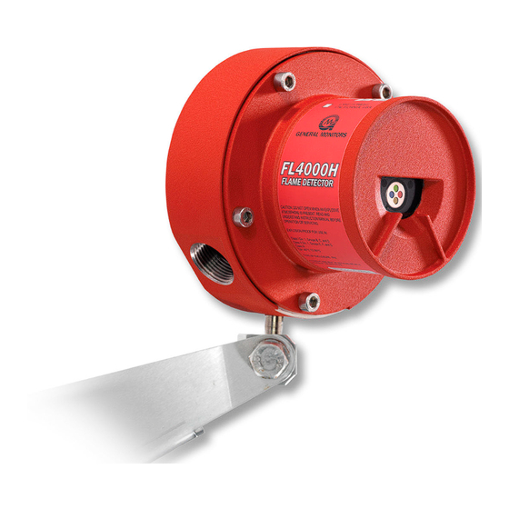
1 Quick Start Guide 1 Quick Start Guide 1.1 Mounting and Wiring the Detector Pay special attention to the conduit seal entry (Canadian Electrical Code Handbook Part 1, Section 18-154). Mount the detector by using the swivel mount or mounting bracket hardware. 1. Loosen the captive screws (A) located on the optical housing assembly. 2. Pull the optical housing assembly from the base housing assembly to separate, gently rock from side to side if necessary to loosen the connector’s grip. 3. Wire the unit to the site-wiring following the connection diagram (Figure 5 ). 4. Reassemble the unit using steps 1 thru 2 in reverse. Figure 1 FL4000H Housing CAUTION! Do not unscrew the field wiring circuit board from the base housing in order to wire the unit. Failure to follow this caution can result in minor or moderate injury. Figure 2 Mounting Instruction Figure 3 Wall Mounting Assembly Model FL4000H... -
Page 6: Applying Power To The Detector
2 Before Installation Figure 4 Bracket Assembly Figure 5 Field Terminations 1.2 Applying Power to the Detector Two light emitting diodes (LED’s) are visible through the window. Immediately upon powering up the detector, both LED’s will start blinking alternately for 15 seconds. The unit will then enter the “Ready” mode. During the “Ready" mode, the green LED will flash off 0.5 seconds every 5 seconds. 1.3 Testing Test the integrity of your system by using a Test Lamp. The original configuration (i.e. sensitivity and relay options) can be changed by referring to 4.7 S witch Selectable Options and then changing the dipswitch settings located on the bottom of the power board (SW1). The instrument is now ready to operate. Consult the Test Lamp manual for more information on the instrument’s many features. If you have any problems in the set-up or testing of the detector, see 7 T roubleshooting, or call the factory direct. 1.4 About this Manual This manual provides instructions for installing, operating, and maintaining the General Monitors (GM) FL4000H Flame Detector. The intended audience includes installation personnel, field service technicians, Modbus programmers, and other technical staff involved in installing and using an FL4000H. Modbus Register Formats Hexadecimal numbers are used in Modbus registers and are indicated by the addition of either “0x” in front of a number or “h” after the number (example: 0x000E or 000Eh, respectively). 2 Before Installation 2.1 System Integrity Verification General Monitors’ mission is to benefit society by providing safety solutions through industry leading products, services, ... -
Page 7: Commissioning Safety Systems
2 Before Installation 2.2 Commissioning Safety Systems Before power up, verify wiring, terminal connections, and stability of the mountings for all essential safety equipment including, but not limited to: • Power supplies • Control modules • Field detection devices • Signaling / output devices • Accessories connected to field and signaling devices After the initial power up and any factory specified warm-up period of the safety system, verify that all signal outputs, to and from the devices and modules, are within the manufacturer’s specifications. Initial calibration / calibration checking / testing should be performed according to the manufacturer’s recommendations and instructions. Proper system operation should be verified by performing a full, functional test of all component devices of the safety system, ensuring that the proper alarm levels occur. Fault / Malfunction circuit operations should be verified. 2.3 Conditions of Use WARNING! • Toxic, combustible, and flammable gases and vapors are dangerous. Extreme caution should be used when these hazards are present. • Keep cover tight while circuits are alive. • Do not open when an explosive atmosphere is present. Failure to follow these warnings can result in serious personal injury or death. •... -
Page 8: Glossary Of Terms
2 Before Installation 2.4 Glossary of Terms Term/Abbreviation Definition Amps Alternating Current Artificial Neural Network American Wire Gauge Baud Rate The number of signal level changes per second in a line, regardless of the information content of those signals Bit per second Cable Armor Cable having interlocked or corrugated armor where it is essential to provide positive grounding of cable armor Cable Screen Mesh surrounding a cable DC Ground COPM Continuous Optical Path Monitoring Control Room Cycle Redundancy Check Direct Current Distributed Control System De-Energized To disconnect from a power source Digital Signal Processor EEPROM Electrically Erasable Programmable Read-Only Memory Electromagnetic Interference Energized To apply voltage or energy Field of View Full Scale General Monitors HART Highway Addressable Remote Transducer-communication protocol Hexadecimal Number Input / Output Instrument Earth... -
Page 9: Product Overview
3 Product Overview Term/Abbreviation Definition OV Return Over voltage return OVDC Power Supply Common Ground Oxidation Combining with Oxygen Printed Circuit Board Programmable Logic Controller Parts per million Radio Frequency Interference Root-Mean-Square Read Only Memory Room Temperature Vulcanization Safety Earth Grounded to the earth Slave One or more devices or processes controlled by a master controller Surface Mount Technology SPAN Value The programmed range of measurable parts per million SPDT Single Pole, Double Throw SPST Single Pole, Single Throw Terminal Block Volts Volts Alternating Current Volts Direct Current Explosion Proof 3 Product Overview 3.1 General Description The General Monitors FL4000H is a MultiSpectral Infrared (MSIR) Flame Detector (Figure 6 ). The FL4000H employs state-of-theart infrared (IR) detectors and a sophisticated artificial neural network (ANN) based signal processing to produce a ... -
Page 10: Applications
3 Product Overview 0-20 mA Analog Output: Transmits alarm and fault indication to a remote display, computer, or other device such as an alarm, dispensing device, or master controller. Dual Redundant Modbus RS-485 User Interface (Standard FL4000H Configuration): Provides the capability to operate the FL4000H remotely, using 2 redundant channels. This interface allows the user to remotely change the alarm and warning relay settings, clear selected faults, clear error counters, change baud rates, and change formats for serial communication lines. HART Protocol (Optional HART Configuration): The HART equipped FL4000H supports the HART communication protocol version 6. Using this protocol, users can transmit diagnostics, settings, and other device status information that improves the efficiency of remote communication. NOTE: FL4000H HART should not be used with General Monitors TA402A and FL802 Controllers. 3.3 Applications The FL4000H provides flame detection for a wide range of applications, including, but not limited to the following: Industries Sample Applications Oil and Gas On and Offshore Platforms Gas Pipelines Compressor Buildings Airports / Military Airplane Hangars Gas Turbines Turbine Enclosures Chemical Plants Process Buildings Loading Terminals Trucking On / Off Loading Areas Petrochemical Process Areas Refineries Tank Farms and Process Areas Table 1 Sample Industry Applications 3.4 ... - Page 11 3 Product Overview State Green Notes Power up 0.5 seconds On 0.5 seconds On Alternating 15 seconds Ready 5 seconds On 0.5 seconds Off Warning 0.5 seconds On 0.5 seconds Off Alarm 0.2 seconds ON 0.2 seconds OFF COPM Fault 0.5 seconds On 0.5 seconds Off Low Voltage, Code or 0.2 seconds ON Date, Checksum Fault 0.2 seconds OFF Test Mode Activated 0.9 seconds ON 0.1 seconds OFF Test Mode Warning 0.5 seconds On 0.5 seconds On Alternating while detecting Test Lamp Test Mode Alarm 02. seconds On 0.2 seconds On Alternating while detecting Test Lamp...
- Page 12 3 Product Overview Each time the Test Mode is activated and the Test Lamp is successfully detected, regardless of which option is used, the FL4000H maintains a timestamp of the test. This timestamp is available to the user via Modbus registers 0x6A, 0x6B, and 0x6C. Test Mode Initiation via Test Lamp NOTE: The Test Lamp sequence is depicted in Figure 7 . When the unit is in Operational Mode, the FL4000H recognizes the Test Lamp as a trigger to activate the Test Mode. Within 5-8 seconds of the Test Lamp flashing, the FL4000H will detect the simulated flame source, drop the analog output to 1.5 mA (3.5 mA with HART and small HART current disabled), and change the LED flashing to indicate “Test Mode Activated” shown in sequence #7 of Table 2 . The relay setting will remain at “Ready” during this operation. Further continuous flashing of the Test Lamp in Test Mode enables the following sequence of events: • After 2 seconds in Test Mode (Phase 2), the FL4000H indicates a Warning condition, by setting the analog output to 16 mA, changing the LED flashing to indicate “Test Mode Running” shown in sequence #8 (Table 2 ), and setting the relay to Warning State. • After a user-selectable time delay of 0-30 seconds (Phase 3), the FL4000H displays an Alarm condition by setting the analog output to 20 mA, and setting the relay to Alarm State. The LED sequence changes to sequence #9 (Table 2 ) “Warning” mode. NOTE: Time delay can be set through Modbus to any value between 0 and 30 seconds, and via dipswitch to 0, 8, 10, or 14 seconds. • After 4.25 minutes in Alarm mode (Phase 4), the unit will return to Ready Mode by dropping the analog output to 4.3 mA, restoring the LED flashing to “Ready” shown in sequence #2 (Table 2 ), and setting the relay to Ready State. The FL4000H has now returned to flame detection status. NOTE: After the test is initiated via the Test Lamp, all other commands are ignored until the Test Mode is over. While in Test Mode, the unit will not detect flames. Interruption of the Test Lamp flashing for more than 3 seconds will result in termination of the test sequence and a return to Ready Mode (Phase 0). If a relay is latched, it must be manually reset via the reset relays line or a Modbus command. There is a 10 second restart delay. After the unit returns to Ready State from Phase 4, the unit waits for 10 seconds before a subsequent Test Lamp transition back to Phase 1. Test Mode Initiation via Grounding of Test Wire or Modbus Command NOTE: Both grounding of the test wire and Modbus command sequence are depicted in Figure 8 . Momentary grounding of a test wire or the Modbus test-mode-enable command causes the FL4000H to enter Test Mode. Initiation of Test Mode is indicated by the analog output dropping to 1.5 mA (3.5 mA with HART and small HART current disabled) and LED flashing in sequence # 7 (Table 2 ). The Test Lamp is not needed to enable Test Mode. If the Test Lamp is not used in Test Mode, the Test Mode times out in 3 minutes. Flashing of the Test Lamp in the Test Mode enabled via test wire or Modbus results in the following sequence of events: •...
- Page 13 3 Product Overview *User setting via dipswitch (0, 8, 10, or 14 seconds) or Modbus (0-30 seconds) ** Factory programmable ***If relay is latched during the test mode, it must be manually reset via reset relays line or Modbus command Figure 7 Test Lamp Flashing Option (Auto-Detection) Model FL4000H...
- Page 14 3 Product Overview *Factory programmable Figure 8 Grounding of Test Wire or Modbus Command Options Model FL4000H...
-
Page 15: Installation
4 Installation 4 Installation WARNING! • The device contains components that can be damaged by static electricity. Always wear grounding apparel when handling or installing the unit. • Only personnel trained and qualified in the HART communication protocol may install and use the HART configuration of the device. • Only trained and authorized users can configure the device. • The device must be installed in accordance with NFPA 72 requirements. Failure to follow these warnings can result in serious personal injury or death. The basic steps in a typical installation are listed in the sections that follow. The installation process may vary depending on the exact site configuration. When used with ULC-listed fire alarm control units equipped with 4-wire smoke detector circuits, the FL4000H should be reset by temporarily removing the supply voltage for at least 70 ms with a decline of operation voltage of no less than 3 VDC. 4.1 Unpacking the Equipment All equipment shipped by General Monitors is packaged in shock absorbing containers that protect against physical damage. The contents should be carefully removed and checked against the enclosed packing list. If any damage has occurred or there is any discrepancy in the order, contact General Monitors. Refer to 8 C ustomer Support for contact information. NOTE: Each FL4000H is completely tested at the factory; however, a system check is required upon initial start-up to guarantee system integrity. 4.2 Required Tools The following tools are required to install the FL4000H: Tool 5mm Allen wrench... - Page 16 4 Installation Horizontal FOV is measured in the horizontal plane going through the center axis of the detector, and vertical FOV is measured in the vertical plane going through the same axis. Both horizontal and vertical FOV are defined for high, medium and low sensitivity settings of the FL4000H, as shown in Figure 9 , Figure 10 , Figure 11 , Figure 12 , Figure 13 , and Figure 14 . Field of View: Horizontal Field of View: Vertical Max Specified Range Max Specified FOV Max Specified Range Max Specified FOV 210 ft (64 m) 90° 230 ft (70 m) 75° 100 ft (31 m) 100° 100 ft (30 m) 80° 30 ft (9 m) 90° 30 ft (9 m) 90° Table 4 Maximum Specified Fields of View at High Sensitivity Figure 9 Horizontal FOV - n-Heptane - Figure 10 Horizontal FOV - n-Heptane - Figure 11 Horizontal FOV - n-Heptane High Sensitivity...
-
Page 17: Detector Mounting And Installation
4 Installation Table 5 Sensitivity Setting for n-Heptane 4.3.3 Environmental Factors • Observe the ambient temperature range for the specific model – refer to 9 .2.5 E nvironmental Specifications. For outdoor installations or other areas exposed to intense, direct solar radiation, the detector may reach temperatures well above specifications. For this condition, a cover for shade may be required to bring the detector temperature within specifications. As with any cover or object near-by, make sure the field of view of the detector is not obstructed. • Avoid conditions of ice build up on the optical detector windows. Complete icing-over of the IR detector window can result in fault conditions. • Modulated reflected sunlight shining at the face of the FL4000H reduces flame detection distance. 4.4 Detector Mounting and Installation The FL4000H is enclosed in an explosion proof assembly, which is rated for use in the environments specified in 9.3.2 Classification Area and Protection Methods. • The unit should be mounted free from shock and vibration and convenient for visual inspection and cleaning. • The detector(s) should be tilted downward so that dust or moisture does not accumulate on the sapphire window. • The detector(s) should be mounted in locations, which will inhibit people or objects from obscuring the detector’s FOV. NOTE: Frequent inspection, cleaning, and sensitivity checking is suggested for detectors mounted in dirty environments. General Monitors requires that the FL4000H conduit entry be sealed per the Canadian Electrical Code Handbook (Part 1, Section 18-154) and NEC Article 501. Conduit seals or approved Ex d glands prevent water or gas from entering the detector’s housing through the conduit entry. Water entering the housing through the conduit entry will damage the electronics and nullify the warranty. -
Page 18: Terminal Connections
4 Installation 1. Loosen the captive screws (A) located on the Optical Housing Assembly. 2. Pull the Optical Housing Assembly from the Base Housing Assembly to separate, gently rock from side to side if necessary to loosen the connector's grip. 3. Make all necessary wiring connections as described in Sections 4.6.1 thru 4.6.12 . NOTE: For an example of wiring, please refer to the connection diagram in Figure 5 . 4. Set switch selectable options as described in 0.1 S witch Selectable Options. Figure 17 FL4000NH Housing 5. Reassemble the unit using steps 1 thru 2 in reverse. WARNING! • Toxic, combustible, and flammable gases and vapors are dangerous. Extreme caution should be used when these hazards are present. • Keep cover tight while circuits are alive. • Do not open when an explosive atmosphere is present. Failure to follow these warnings can result in serious personal injury or death. 4.6 Terminal Connections 1. ... - Page 19 4 Installation Terminal Block - P2 Terminal Block - P1 Pin # Description Pin # Description WARN2 FLT 2 WARN1 FLT 1 WARN C FLT C ALM C TEST_10 (Test Mode) ALM 1 COM1+/DATA1+ ALM 2 COM1-/DATA1- RLY_10 (Relay Reset) 7 0-20mA COM2+/DATA2+ +24 V COM2-/DATA2- GND/COM CAL_ IO CHGND/CHASGND (Chassis Ground) Table 6 Terminal Block Connections There are twenty possible terminal connections. Sections 4.6.1 , 4.6.2 , and 4.6.4 provide a description and specification for each connection. 4.6.1 Alarm Relay Terminal Block Connection Point Block Name User Relay Settings...
- Page 20 4 Installation 4.6.2 Warning Relay Terminal Block Connection Point Block Name User Relay Settings Normally De- Normally Energized Energized Term 8 WARNC Warn Common Warn Common Term 9 WARN1 Warn NC Warn NO Term 10 WARN2 Warn NO Warn NC NOTE: NO - Normally Open; NC = Normally Closed Table 8 Warning Relay Terminals Description: These connections are to the SPDT WARN relay. The WARN output is immediate on the FL4000H. The WARN output can be normally energized or de-energized, latching, or non-latching. These options are also set via Modbus or by a dipswitch (0.1 S witch Selectable Options). The WARN relay contact ratings are 8 A @ 250 VAC and 8 A @ 30 VDC. Refer to Figure 20 for all relay connections. 4.6.3 Alarm Wiring Relay Protection Inductive loads (bells, buzzers, relay, contractors, solenoid valves, etc.) connected to the Alarm, Warn, and Fault relays ...
- Page 21 4 Installation The FAULT circuit will be activated during the time-out function, a low power or loss of power condition, or during a failed COPM check. During these conditions, the FAULT relays will de-energize and the analog output signal will drop to 0 mA (2 mA for COPM Faults, 3.5 mA with HART or 1.25 mA for HART with small current enabled) for the duration of the FAULT. The FAULT relay contact ratings are 8 A @ 250 VAC and 8 A @ 30 VDC. Refer to Figure 20 for all relay connections. 4.6.5 Alarm Reset Terminal Terminal Block Connection Point Block Name Setting Term 4 RLY_IO Relay Reset Table 10 Alarm Reset Terminal The RESET, when activated, returns a latched ALARM and/or WARN output that is no longer valid to its original state. For this RESET function, place one contact of a SPST (single pole, single throw), normally open, momentary switch to P2 Terminal 4 and the other contact to P1 terminal 9 (GND). To activate, press and release the switch. 4.6.6 Test Mode Terminal Terminal Block Connection Point Block Name Setting Term 4 TEST_IO Test Mode Table 11 Test Mode Terminal By connecting one contact of a SPST, normally open, momentary switch to P1 terminal 4 and the other contact to P1 terminal 9 (GND), the user can put the unit into a special test mode. When the switch is first closed, the mode is set and the FL4000H goes to 1.5 mA or 3.5 mA with HART and small HART current disabled (ready mode) and remains at this value ...
- Page 22 4 Installation NOTE: All switches are momentarily ON Figure 22 Wiring Diagram - Reset Relays, Test Mode, and Alarm Test 4.6.8 Analog Output Terminal Block Connection Point Block Name Setting Term 7 0-20 mA Analog Output Table 13 Analog Output Terminal The 0 to 20 mA output is a current signal that corresponds to the following: Analog Output Dual Modbus HART (3.5 mA) HART (1.25 mA) Startup* 0 to 0.2 mA 3.5 mA 1.25 mA FAULT Signal 0 to 0.2 mA 3.5 mA 1.25 mA Test Mode...
-
Page 23: Switch Selectable Options
4 Installation 4.6.10 P ower Terminal Block Connection Point Block Name Setting Term 8 +24IN +24 V (VDC) Term 9 Ground (COM) Table 16 Power Terminals 4.6.10 shows the power connections for the FL4000H. The supply voltage range is 20 to 36 VDC at the detector (low voltage is detected at 18.5 VDC). The following maximum cable lengths apply for a +24 VDC supply (maximum 20 Ω loop): Feet Meters 4,500 1,370 2,340 1,540 Table 17 Maximum Cable Lengths for +24 VDC 4.6.11 M odbus (RS-485) Output Terminal Block Connection Point Setting Term 5 COM1+ (A) -
Page 24: Powering Of The Fl4000H
4 Installation 4.7.1 Time Delay Settings Time delay set via dipswitch (A) guarantees that FL4000H will not go into ALARM mode (20 mA) if the flame source is removed within 50% of set delay time from the start of flame. The unit will always go into WARN mode (16 mA) upon seeing a flame source. Figure 23 Dipswitch Location Option On/Closed Off/Open High Sensitivity 1 and 2 Medium Sensitivity Low Sensitivity 0-Second Alarm Time Delay 3 and 4 8-Second Alarm Time Delay 10-Second Alarm Time Delay 3 and 4 14-Second Alarm Time Delay ALARM Non-Latching ALARM Latching WARN Non-Latching WARN Latching ALARM Normally Energized ALARM Normally De-Energized WARN Normally Energized ... -
Page 25: Modbus Interface
5 Modbus Interface 5 Modbus Interface 5.1 Introduction The FL4000H provides communicating ability via the industry standard Modbus protocol, while acting as the slave device in a typical master/slave configuration. Upon receiving an appropriate query from the master, the FL4000H will respond with a formatted message as defined below. 5.2 Communication Slave Address The FL4000H communication slave address is a unique ID used by the Modbus protocol to identify each unit on a multi drop Modbus communication bus. The address may contain the values 1 – 247. There are two communication channels on the FL4000H. Each channel may have a separate slave address. The default slave address for each channel is 1. Register 0x09 is used to modify the address for channel COM1 and register 0x2F is used to modify the address for channel COM2. 5.3 Baud Rate The FL4000H baud rate is selectable using either the Modbus communications interface. The selectable baud rates are 38,400, 19,200, 9,600, 4,800, or 2,400 bits per second (bps). The factory set baud rate is 19,200 bps. Register 0x0B is used to modify the baud rate for comm channel 1 and register 0x30 is used to modify the baud rate for comm channel 2. See Table 21 for selectable baud rate. Modbus Register Value Baud Rate (bps) 38,400 19,200 9,600 4,800 2,400 Table 21 Selectable Baud Rates 5.4 Data Format The data format is selectable using the Modbus communications interface. The factory set data format is 8-N-1. Register 0x0C is used to modify the data format for comm channel 1 and register 0x31 is used to modify the format for comm channel 2. See Table 22 for selectable data formats. Modbus Register Value Format Data Bits Parity Stop 8-N-1... -
Page 26: Modbus Write Command Protocol (Query/Response)
5 Modbus Interface Byte Modbus Range Referenced to FL4000H Slave Address 1-247* (Decimal) FL4000H ID (Address) Function Code Read Holding Registers Starting Address Hi Not Used by the FL4000H Starting Address Lo 00-44 (Hex) FL4000H Commands Number of Registers Hi Not Used by the FL4000H Number of Registers Lo** 01- 45 (Hex) Number of 16 Bit Registers CRC Lo 00-FF (Hex) CRC Lo Byte CRC Hi 00-FF (Hex) CRC Hi Byte * Address 0 is reserved for Broadcast Mode and is not supported at this time. ** A maximum of 69 registers can be requested during a single block of time. Table 23 Modbus Read Register(s) Request Upon receiving a valid read register request from the master device, the FL4000H will respond with a message (Table 24 ). If the query generates an error, an exception message is returned to the master device (5.8 E xception Responses and Exception Codes). -
Page 27: Exception Responses And Exception Codes
5 Modbus Interface Upon receiving a valid register write request from the master device, the FL4000H will respond with a message (Table 26 ). If the write request generates an error, an exception message is returned to the master device (5.8 E xception Responses and Exception Codes). Byte Modbus Range Referenced to FL4000H Slave Address 1-247* (Decimal) FL4000H ID (Address) Function Code Preset Single Registers Register Address Hi 00 Not Used by the FL4000H Register Address Lo 00-44 (Hex) FL4000H Register Address Lo Byte Preset Data Hi 00-FF (Hex) FL4000H Hi Byte Command Data Preset Data Lo 00-FF (Hex) FL4000H Lo Byte Command Data CRC Lo 00-FF (Hex) CRC Hi Byte CRC Hi 00-FF (Hex) CRC Lo Byte * Address 0 is reserved for Broadcast Mode and is not supported at this time. Table 26 Modbus Write Register Response 5.8 ... -
Page 28: Command Register Locations
5 Modbus Interface 5.8.2 Exception Code Exception Code Field: In a normal response, the FL4000H returns data and status in the response data field. In an exception response, the FL4000H returns an exception code (describing the FL4000H condition) in the data field. Below is a list of exception codes that are supported by the FL4000H: Code Name Description Illegal Function The function code received in the query is not an allowable action for the FL4000H. Illegal Data Address The data address received in the query is not an allowable address for the FL4000H Illegal Data Value A value contained in the query data is not an allowable value for the FL4000H. Reserved Table 28 Exception Codes 5.9 Command Register Locations Table 29 Command Register Locations Register Parameter Function Date Type Data Range Access Address (Hex) 0x0000 Analog Output 0-20mA current output Numeric ... - Page 29 5 Modbus Interface Register Parameter Function Date Type Data Range Access Address (Hex) 0x0012 Remote Alarm Test Activates Warn & Alarm Relays Numeric 1 = Alarm test, 0 = done test Value 0x0013 Clear COPM Fault Reset COPM Counters to zero Bit Map Bit 1 = Reset Counts 0x0013 Sensor Temperature Temperature in Degrees C Numeric -128...+128 Value 0x0015 - Reserved 0x001C 0x001D HART Enable/disable HART Numeric 0 - disable Enable/Disable Value 1 - enable 0x001E - ...
- Page 30 5 Modbus Interface Register Parameter Function Date Type Data Range Access Address (Hex) 0x0047 Real Time Clock Read/Set year and month of RTC Numeric Year, Month Value 0x0048 Real Time Clock Read/Set day and hour of RTC Numeric Day, Hour Value 0x0049 Real Time Clock Read/Set minutes and seconds of Numeric Minute, Second Value 0x004A – Reserved 0x0059 0x005A TEST LAMP Test Set/Reset TEST LAMP test mode. 0 = ...
-
Page 31: Command Register Details
5 Modbus Interface Register Parameter Function Date Type Data Range Access Address (Hex) 0x00AF Reserved Reserved Numeric Value 0x00B0 Alarm Event Count Total Alarm Event Count Numeric 0 - 65535 Value 0x00B1 Running Time Hi Running Time Hi for Fault Event log Numeric 0 - 65535 entries Value 0x00B2 Running Time Low Running Time Low for Fault Event log Numeric 0 - 65535 entries Value 0x00B3 Clock Time Hi Hi byte = year, Lo byte month: Fault Numeric 1 –99 year, ... - Page 32 5 Modbus Interface Mode Decimal Value Power-Up Delay Warn Non-Latching Only Warn and Alarm Non-Latching Warn Latching Only, Alarm Off Alarm Latching Only Warn and Alarm Latching Ready State Alarm Test COPM Fault Detected Warn Latching, Alarm Non-Latching, Alarm On 12 TEST LAMP Cycle TEST LAMP Cycle - Fire Table 30 Status Mode Values 5.10.3 ( Register 0x0002) Status/Error A read returns the errors that are present, which are indicated by bit position. Table 31 shows the error code returned via the Modbus register 2: Function Decimal Value COPM Low Voltage Data Flash Checksum 6 Code Flash Checksum 7 Relay Reset Shorted NOTE: Bits set to “1” when errors occur. Table 31 Modbus Error Codes 5.10.4 ...
- Page 33 5 Modbus Interface and Relay Energized/De-Energized features are controlled by the data stored in FLASH and are not controlled by the 8- position dipswitch. When the dipswitch override bit is disabled the options are under the control of the 8- position dipswitch. The override bit is located in the LSB of the Low Data Byte and the High Data Byte is not used. • Bit = 1, Enabled: Configured from FLASH • Bit = 0, Disabled: Configured from DIP Switch NOTE: By grounding the TEST input during the first 1 second of the power up cycle, the FL4000H will enable the DIP Switch Override, enabling the 8-position Dip Switch settings to take effect. The DIP Switch Override bit will be set to zero after approximately 1 second, at which time this input can be released from ground. A 01 Low Sensitivity 10 Med Sensitivity 11 High Sensitivity 0 (Not Use) B 00 0-Sec Alarm Time Delay 01 8-Sec Alarm Time Delay 10 10-Sec Alarm Time Delay 11 14-Sec Alarm Time Delay C 0 ALARM Latching 1 ALARM Non-Latching D 0 WARN Latching 1 WARN Non-Latching E 0 ALARM Normally Energized 1 ALARM Normally De-Energized F 0 ALARM Normally Energized 1 ALARM Normally De-Energized G 0 WARN Normally Energized 1 WARN Normally De-Energized Figure 24 Command Register (0x0007, Dipswitch Override) 5.10.8 ...
- Page 34 5 Modbus Interface and green LED’s flash alternately after approximately 1 second, at which time the RESET input can be released from ground. 5.10.10 COM1 Baud Rate (0x000B) A read command returns the current baud rate for COM1 channel. A write command changes the baud rate to the requested values. Valid settings are shown in Table 32 . Factory default is 19,200 baud. Baud Rate Value Access 2,400 Read / Write 4,800 Read / Write 9,600 Read / Write 19,200 Read / Write 38,400 Read / Write Table 32 Com1 Baud Rate NOTE: If the baud rate is not in range, an Illegal Data Value (03) is returned. By grounding the RESET input during the first 1 second of the power up cycle, the FL4000H Baud Rate will default to 19.2K. The baud rate will be set to a default of 19.2K when the red and green LED’s flash alternately after approximately 1 second, at which time the RESET input can be released from ground. 5.10.11 COM1 Date Format (0x000C) A read command returns the current data format for COM1 channel. Write command changes the data format to the requested values. Valid settings are shown in Table 33 . Default format is 8-N-1. Format Parity Stop Data Bits Value Access 8-N-1 None...
- Page 35 5 Modbus Interface 5.10.15 COPM Counts Sensor 4 (0x0010) A read indicates the number of COPM Faults that have occurred for sensor 4 in the FL4000H. Refer to 3.4.2 C ontinuous Optical Path Monitoring - COPM Circuitry for more information on COPM and 7 T roubleshooting for troubleshooting tips. 5.10.16 Remote Reset (0x0011) Writing a 1 to the register activates the Remote Reset function, which resets the Alarm and Warn Relays. The function is active momentarily and will reset automatically after being used. 5.10.17 Remote Alarm Test (0x0012) Writing a 1 to the register activates the Remote Alarm Test function, which activates the Warn and Alarm Relays. In addition, the function also activates the corresponding LED sequence and analog output. Upon completion of the test, a zero should be written to the register to conclude the Alarm Test. If the relays are configured in a latching configuration, refer to 5.10.16 R emote Reset (0x0011) to reset the relays and the alarm condition. 5.10.18 Clear COPM Faults (0x0013) Writing a 1 to the register activates the Clear COPM Faults function that resets all of the detector fault counters. 5.10.19 Sensor Temperature Output (0x0014) Reading this register retrieves the sensor temperature in degrees Celsius. The range is –128 to +128. 5.10.20 HART Enable/Disable (0x001D) This command enables or disables the HART. A ‘0’ is to disable and a ‘1’ is to enable. 5.10.21 Total Receive Errors – COM1 or COM2 (0x0020) A read indicates the total Modbus COM1 or COM2 channel receive errors in the FL4000H. The maximum count is 65535, after which the counter resets to zero and begins counting anew. The total errors are an accumulation of all communication errors. 5.10.22 Data Errors – COM1 and COM2 (0x0021) A read indicates the number of illegal data write errors on user Modbus. These are errors where the write value is out of range. The maximum count is 65535, after which the counter resets to zero and begins counting anew.
- Page 36 5 Modbus Interface 5.10.27 CRC Errors Hi – COM1 and COM2 (0x0026) A read indicates the number of COM1 and COM2 CRC Hi byte errors that occurred in the FL4000H. The maximum count is 65535, after which the counter resets to zero and begins counting anew 5.10.28 Total Overrun Errors – COM1 only (0x0027) A read indicates the number of COM1 Overrun Errors that occurred in the FL4000H. The maximum count is 65535, after which the counter resets to zero and begins counting anew. NOTE: An overrun error occurs when a subsequent received data byte overwrites an earlier unprocessed data byte. As a result, one of the received data bytes will be corrupted. 5.10.29 Total Framing Errors – COM1 and COM2 (0x0029) A read indicates the number of Comm 1 and Comm 2 Framing Errors that occurred in the FL4000H. The maximum count is 65535, after which the counter resets to zero and begins counting anew. 5.10.30 Clear Communication Errors (0x002D) A read indicates the total number of Modbus communication errors. The maximum count is 65535, after which the counter resets to zero and begins counting anew. A write resets this value to 0. Only a write of value “0” is allowed for this register. 5.10.31 4.10.31 Enable/disable small HART current (0x002E) Normally in HART mode the analog output current does not go below 3.5 mA and register 0x2E reads 0. If a value of 1 is written to the register 0x2E, the minimum HART current becomes 1.25 mA. This allows to distinguish several operating modes that have output current below 3.5 mA. 5.10.32 COM2 Address (0x002F) A read returns the COM2 address of the FL4000H. A write changes the address to the requested number. The range of the address is from 1 to 247 (01 to F7 in Hex). After changing the address of the FL4000H, it will be necessary for the controlling or master device to similarly change its query address in order to once again communicate with the FL4000H. NOTE: By grounding the RESET input during the power-up cycle (approximately 10 seconds), the address of the FL4000H will default to 1. 5.10.33 COM2 Baud Rate (0x0030) A read returns the COM2 baud rate of the FL4000H. A write changes the baud rate to the requested level. After changing the baud rate of the FL4000H, it will be necessary for the controlling or master device to similarly change its own baud rate in order to once again communicate with the FL4000H. NOTE: By grounding the RESET input during the power-up cycle (approximately 10 seconds), the baud rate of the FL4000H will default to 19.2K. Valid settings are shown in Table 32 . 5.10.34 ...
- Page 37 5 Modbus Interface 5.10.36 Set/Read Real-time Clock Day, Hour (0x0048) This is used to read/write the real time clock. The high byte will be the day of the month from 1 to 31. The low byte will be the hour from 0 to 23. 5.10.37 Set/Read Real-time Clock Minute, Second (0x0049) This is used to read/write the real time clock. The high byte will be the minute from 0 to 59 and the low byte will be the seconds from 0 to 59. NOTE: The registers when read, should be read in order: first 47, then 48, then 49. When written, they should be written in order: first 47, then 48, and finally 49. 5.10.38 Set/Reset TEST LAMP Test Mode (0x005A) This is used to place the unit into Test Lamp test mode or return it to the normal mode. Writing a 1 to the register places the unit into test mode. Writing a 0 to the register places it back into normal mode. Refer to 4.6.6 T est Mode Terminal. 5.10.39 TEST LAMP Alarm Delay Using the dipswitches, the alarm delay may be set to one of four pre-programmed settings (0, 8, 10, or 14 seconds). Register 0x5B is used to set the alarm delay to any desired value from 0 to 30 seconds. The dipswitch override flag must be set to 1. NOTE: If the user writes to this register, it overrides the value set by bits 2 and 3 of register 8. Reading register 8 will simply return the last values in bits 2 and 3 that will not show the value written to this register. This behavior is intentional and is to provide backward compatibility with other General Monitors’ flame detectors. 5.10.40 Power Cycle Flag (0x009A) This reads whether the time of day clock has been reset after a power has been re-cycled to the unit. If the time has been reset, this flag will be = 0; otherwise the flag will = 1. 5.10.41 Event Index (0x00A0) This is used to indicate which of the stored events the user would like to read. There are 4 event logs maintained by the FL4000H unit: Warning events, Alarm events, Fault events, and Maintenance events. Each of these event logs consist of 10 of their most recent occurrences. The user is able to read the times of each of these by setting this event index followed by a reading of the desired event log. The event index is a number from 0 to 9. Zero refers to the most recent event and 9 refers to the least recent event stored in the log. For example to read the most recent Warning event in the Warning event log, set this register to 0 and then read registers 0xA1 and 0xA2 (for the running time in seconds) or read registers 0xA3, 0xA4, and 0xA5 (for the clock time). There is also a warning counter which gives the total number of warnings received by the system (with a maximum of 65535).
- Page 38 5 Modbus Interface Table 34 Event Log Clock Time Format NOTE: The values from Table 34 should be read in order: first item 1, then item 2, & then item 3. 5.10.44 Warning Clock Time: Year, Month (0x00A3) These registers are described in Table 34 as item number 1. 5.10.45 Warning Clock Time: Day, Hour (0x00A4) These registers are described in Table 34 as item number 2. 5.10.46 Warning Clock Time: Minute, Second (0x00A5) These registers are described in Table 34 as item number 3. 5.10.47 Reserved (0x00A6) This register returns the value 0. 5.10.48 Reserved (0x00A7) This register returns the value 0 5.10.49 Total Warning Event Counter (0x00A8) This reads the total number of warning events have been stored in the unit. 5.10.50 Alarm Running Time in Seconds, Hi Word (0x00A9) This register reads the hi word of the running time in seconds when the alarm event occurred. This time is in seconds since January 1, 2000. This register should be read before register 0xAA. 5.10.51 Alarm Running Time in Seconds, Low Word (0x00AA) This register reads the low word of the running time in seconds when the alarm event occurred. This time is in seconds since January 1, 2000. This register should be read only after register 0xA9. 5.10.52 Alarm Clock Time: Year, Month (0x00AB) These registers are described in Table 34 as item number 1. 5.10.53 ...
- Page 39 5 Modbus Interface 5.10.58 Fault Running Time in Seconds, Hi Word (0x00B1) This register reads the hi word of the running time in seconds when the fault event occurred. This time is in seconds since January 1, 2000. This register should be read before register 0xB2. 5.10.59 Fault Running Time in Seconds, Low Word (0x00B2) This register reads the low word of the running time in seconds when the fault event occurred. This time is in seconds since January 1, 2000. This register should be read only after register 0xB1. 5.10.60 Fault Clock Time: Year, Month (0x00B3) These registers are described in Table 34 as item number 1. 5.10.61 Fault Clock Time: Day, Hour (0x00B4) These registers are described in Table 34 as item number 2. 5.10.62 Fault Clock Time: Minute, Seconds (0x00B5) These registers are described in Table 34 as item number 3. 5.10.63 Fault Code (0x00B6) This register is described in Table 31 . 5.10.64 Reserved (0x00B7) This register returns the value 0. 5.10.65 Total Fault Event Counter (0x00B8) This reads the total number of fault events have been stored in the unit. 5.10.66 Maintenance Running Time in Seconds, Hi Word (0x00BA) This register reads the hi word of the running time in seconds when the maintenance event occurred. This time is in seconds since January 1, 2000. This register should be read before register 0xBB. 5.10.67 Maintenance Running Time in Seconds, Low Word (0x00BB) This register reads the low word of the running time in seconds when the maintenance event occurred. This time is in seconds since January 1, 2000. This register should only be read after register 0xBA. 5.10.68 Maintenance Clock Time: Year, Month (0x00BC) These registers are described in Table 34 as item number 1. 5.10.69 ...
- Page 40 5 Modbus Interface 5.10.72 Total Maintenance Event Counter (0x00C0) This reads the total number of maintenance events have been stored in the unit. 5.10.73 Reset All Event Counters (0x00C1) Writing to this register resets all event counters to zero. Model FL4000H...
-
Page 41: Maintenance
6 Maintenance 6 Maintenance WARNING! • Use only genuine MSA replacement parts when performing any maintenance procedures provided in this manual. Failure to do so may seriously impair sensor performance, alter flameproof/explosionproof characteristics, or void agency approvals. Failure to follow this warning could cause the product to fail to perform as designed and persons who rely on this product for their safety could sustain serious personal injury or loss of life. • Repair or alteration of the device, beyond the scope of maintenance procedures provided in this manual or by anyone other than authorized MSA service personnel, could cause the product to fail to p erform as designed and persons who rely on this product for their safety could sustain serious personal injury or loss of life. Failure to follow these warnings can result in serious personal injury or death. 6.1 General Maintenance Once correctly installed, the unit requires very little maintenance other than regular sensitivity checks and cleaning of the window. General Monitors recommends that a schedule be established and followed. Do not remove the electronics from the housing. Doing so will void the equipment’s warranty. NOTE: The removal of particulate matter and any film buildup on the Sapphire Window and COPM Reflector is necessary to ensure proper sensitivity of the system. It is recommended that the window and reflector be cleaned at least every 30 days if the detector is located in a particularly dirty environment. 6.2 Cleaning the Sapphire Window A clean, soft, lint-free cloth, tissue or cotton swab should be used to apply the cleaning solution. The window is not glass; it is made from sapphire. The cleaning solution should be General Monitors’ P/N 10272-1 (Industrial Strength Windex with Ammonia D). Do not touch the window or COPM reflector with fingers. 1. Wet the window with the solution. -
Page 42: Sensitivity Check
7 Troubleshooting 6.3 Sensitivity Check To verify that each detector is functioning correctly, a General Monitors’ Test Lamp and/or the ALARM TEST function (4.6.7 A larm Test Terminals) should be used. Refer to 9.5.2 T est Lamp for details on Test Lamps. 6.4 Storage The FL4000H should be stored in a clean, dry area and within the temperature and humidity ranges quoted in 9.2.5 Environmental Specifications. 7 Troubleshooting 7.1 Troubleshooting Chart This section is intended to be a guide to correcting problems, which may arise in the field. General Monitors should be contacted for assistance if the corrective action listed does not eliminate the problem. Defective units should be returned to General Monitors for repair with a complete written description of the problem. NOTE: If the equipment is under warranty, any repairs performed by persons other than General Monitors’ authorized personnel may void the warranty. Please read the warranty statement carefully. CAUTION! Be sure to inhibit or disconnect external alarm wiring before making any check that might send the unit into alarm. Failure to follow this caution can result in minor or moderate injury. Problem Possible Cause Corrective Action Analog output signal = 0 mA and No DC power to unit Be sure that the +24 VDC is applied green LED in window is off with the correct polarity Analog output signal = 0 mA (3.5 or ... -
Page 43: Final Assembly
7 Troubleshooting 7.2 Final Assembly A Optical Housing Assembly B Sapphire Window C Label D O-Ring E Base Housing F Field Wiring Board G Mounting Pin H Modular Power Board I Modular Communication Board J Modular Processor Board K Analog Board Figure 26 FL4000H Cross-Section View Model FL4000H... -
Page 44: Customer Support
IRELAND Ballybrit Business Park Phone: +353-91-751175 Galway Fax: +353-91-751317 Republic of Ireland H91 H6Ps Email: info.gmil@MSAsafety.com SINGAPORE 35 Marsiling Industrial Estate Road 3, #04-01 Phone: +65-6350 4500 Singapore 739257 Email: msa.singapore@MSAsafety.com MIDDLE EAST PO Box 54910 Dubai Airport Free Zone Phone: +971-299-6741 United Arab Emirates Email: gmdubai.main@MSAsafety.com Table 36 GM Locations Additional locations can be found on our web site, www.MSAsafety.com 8.2 Other Sources of Help Extensive documentation, white papers, and product literature for our complete line of safety products can be found at http://www.MSAsafety.com/detection Model FL4000H... - Page 45 9 Appendix 9 Appendix 9.1 Warranty General Monitors warrants the FL4000H to be free from defects in workmanship or material under normal use and service within two (2) years from the date of shipment. General Monitors will repair or replace without charge any equipment found to be defective during the warranty period. Full determination of the nature of, and responsibility for, defective or damaged equipment will be made by General Monitors’ personnel. Defective or damaged equipment must be shipped prepaid to General Monitors or the representative from which shipment was made. In all cases, this warranty is limited to the cost of the equipment supplied by General Monitors. The customer will assume all liability for the misuse of this equipment by its employees or other personnel. All warranties are contingent upon proper use in the application for which the product was intended and do not cover products which have been modified or repaired without General Monitors’ approval or which have been subjected to neglect, accident, improper installation or application, or on which the original identification marks have been removed or altered. Except for the express warranty stated above, General Monitors disclaims all warranties with regard to the products sold, including all implied warranties of merchantability and fitness and the express warranties stated herein are in lieu of all obligations or liabilities on the part of General Monitors for damages including, but not limited to, consequential damages arising out of / or in connection with the use or performance of the product. 9.2 Specifications 9.2.1 System Specifications Typical Response Time ≤ 10 sec for heptane fires when detector is on axis to fire source; ≤ 30 sec when detector is at angles of ±45º Field of View* 90° @ 210 ft (64 m), 100° @ 100 ft (31 m) Sensitivity 60 ft (18 m), 120 ft (37 m), and 210 ft (64 m) for low, medium, and high sensitivities, respectively. Maximum distance for a 1 square foot (0.093 m2 ) n-heptane fire to be reliably detected. For settings see 4.7 S witch Selectable Options. Maximum specified FOV is the angle at which FL4000H can detect the flame at 50% of the maximum specified range. To comply with the directional dependence requirements for EN 54-10:2002, an angle of ± 35° from 0°(0° = Orientation of detector in same axes as flame source) should not be exceeded, based on lab testing at a distance of approximately 5.9 ft (1.8 m). NOTE: Response Times and Field of View data were obtained from tests with a 1 square foot heptane fire. These are ...
- Page 46 9 Appendix 9.2.4 Electrical Specifications Nominal supply voltage: 24 VDC (135 mA, 3.2W Max @ 24 VDC) Range: 20 to 36 VDC Maximum supply current: 160 mA (during COPM only) Maximum power consumption: 4.4W Spectral Range: 2 – 5 microns (IR) Maximum output signal load: 600 Ω @ 24 VDC Dual Modbus HART HART (small current) Output signal range: 0 to 20 mA 3.5 – 20 mA 1.25 – 20 mA FAULT signal: 0 to 0.2 mA 3.5 mA 1.25 mA COPM fault signal: 2.0 ± 0.2 mA 3.5 mA 2.0 ± 0.2 mA Ready signal: 4.3 ± 0.2 mA WARN signal: 16.0 ± 0.2 mA ALARM signal: 20.0 ± 0.2 mA ...
- Page 47 9 Appendix 9.3 Regulatory Information 9.3.1 Approvals Approvals Standard Configuration* HART ATEX (CML 23ATEX1034X)** UKCA ( CML 23UKEX1042X)** IECEx (CML 23.0014X)** HART Communication Foundation (HCF) CPR (2809-CPR-E0001)*** UKCP ( 1725-CPR-E1001)*** INMETRO (NCC 12.1178X) IEC 6 1508 to SIL 3, 2 or 1 ESMA/EQM *Dual Modbus with or without relays ** The applicable compliance standards are listed on the product certificates which can be obtained via our website ***Listed as Class 1 for High and Medium Sensitivity and Class 2 for Low Sensitivity 9.3.2 Classification Area and Protection Methods The FL4000H is certified as follows: Protection Method Explosion proof, Flame proof, Dust-Ignition proof Temperature Class T5 (T =-40°C to +80°C Area Classifications Class I, Division1, Groups B, C, and D Class II, Division1, Groups E, F, and G Class III Zone 1, Group IIC per ATEX/UKCA/IECEx Zone 21, Group IIIC per ATEX/UKCA/IECEx Ex db IIC T5 Gb, Ex tb IIIC T100°C Db...
- Page 48 9 Appendix False Alarm Source Distance ft (m) Modulated Distance ft (m) Unmodulated Response Response Heater 6 (1.8) No alarm 1 (0.3) 100 W incandescent bulb 1 (0.3) No alarm 1 (0.3) No alarm Fluorescent lamp (2 40- <1 (0.3) No alarm <1 (0.3) No alarm W bulbs) 500 W halogen lamp 2 (0.6) No alarm < 1 (0.3) No alarm Sunlight (reflected) 6 (1.8) No alarm 6 (1.8) No alarm Sunlight (direct) No alarm No alarm Hot plate (200°C) 3 (0.9) No alarm 1 (0.3) No alarm...
- Page 49 9 Appendix NOTE: In general, the operator should try to avoid exposing the detector to false alarm sources. Many false stimuli such as welding or heaters emit high amounts of IR radiation, which tend to degrade the performance of the instrument. 9.5 Spare Parts and Accessories When ordering Spare Parts and/or Accessories, contact a Representative or General Monitors directly with the following information: • Part Number • Description • Quantity 9.5.1 Spare Parts Item Description Part Number Window Cleaning Solution 10272-1 Bracket Assembly 71370-1 Instruction Manual MANFL4000NH Test Lamp 71655-1 Mounting Bracket 71313-1 Rain Guard Kit 712006-1 9.5.2 Test Lamp Due to the advanced discrimination of the FL4000H, the TL105 Test Lamp was developed. The Test Lamp is a battery operated, rechargeable, test source specifically designed to test General Monitors’ IR Flame Detection Systems. It consists of a high energy broadband radiation source that emits sufficient energy in the infrared spectra to activate the IR detector. To simulate a fire, the TL105 Test Lamp automatically flashes a signal that the FL4000H recognizes. The lamp must be set to rotary switch position “4” to be recognized by the FL4000H. See Appendix A for details. Operating Instructions The FL4000H has the ability to be put into a special test mode activated state by momentarily grounding the test mode pin on the unit or by issuing a Modbus write command to register 0x5A. The unit will respond by going into this test mode activated state and by blinking a unique flashing pattern with the green LED on for 0.9 seconds and off for 0.1 seconds. The ...
- Page 50 10 Appendix A Recharging Instructions NOTE: Charging must be carried out in a non-hazardous area. The charging receptacle is located inside the housing adjacent to the ON button. To gain access, it is necessary to unscrew the knurled plug from the body of the unit. The plug is secured to the ON button by a safety strap to keep it from being lost. Insert the charging plug into the receptacle. Complete recharging takes 3.5 hours, minimum. NOTE: Replace the plug after charging is complete. It is recommended that the Test Lamp be kept on charge when not in use to prevent excessive battery discharge. The batteries may be charged an average of 500 times before the battery pack must be replaced. 9.5.3 Mounting Bracket A mounting bracket is available to mount the FL4000H to a wall, pole, etc. The mounting bracket design allows for optical alignment adjustments when utilizing to a fixed installation. Refer to Figure 15 . 9.5.4 Rain Guard A rain guard is available for the FL4000H. Install the rain guard per instruction sheet 712013. *FL4000/H is shown for reference only Figure 27 Rain Guard Installation 10 Appendix A *Rotary Switch shown in position 1 for testing FL3100 Flame Detectors (for FL4000H use position 4) Figure 28 Functional Board Located Under TL105 Lamp Assembly Model FL4000H...
- Page 51 10 Appendix A Flame Detector to Test Rotary Switch Setting Maximum Distance to Results Detector (ft) UV & UV/IR Type V & VI UV & UV/IR Type V & VI triggers into alarm mode FL3000 FL3000 triggers into alarm mode FL3001 FL3001 triggers into alarm mode FL3002 FL3002 triggers into alarm mode FL3100 FL3100 triggers into alarm mode FL3101 FL3101 triggers into alarm mode FL3102 FL3102 triggers into alarm mode FL3110 FL3110 triggers into alarm mode FL3111 FL3111 triggers into alarm mode FL3112 FL3112 triggers into alarm mode FL4000H 35 (High Sensitivity) FL4000H enters test mode 18 (Medium Sensitivity)
- Page 52 For local MSA contacts, please visit us at MSAsafety.com...
Need help?
Do you have a question about the General Monitors FL4000H and is the answer not in the manual?
Questions and answers