Table of Contents
Advertisement
Quick Links
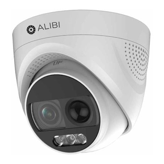
ALI-TP1002LS 2 MP
Camera with Strobe and Siren
Quick Installation Guide
The ALIBI ALI-TP1002LS indoor / outdoor turret camera includes a 4 -in-1 switchable video output (TVI/
AHD/CVI/CVBS) with a 2 MP sensor and Starlight technology for color vision at night. This camera features:
2 Megapixel (1920 1080 pixels) wyth CMOS sensor
•
Switchable video output for TVI, AHD, CVI, or CVBS (4 in 1)
•
24 hour color image
•
Starlight 2.0 chipset
•
3.6 mm fixed lens offers horizontal FOV of 83.6°
•
True WDR up to 130 dB
•
PIR Detection, Strobe light alarm, alarm out / audible siren alarm
•
IP67 weather-rated with -40°F – 140°F operating temperatures
•
OSD menu (up-the-coax OSD control)
•
Compatible with ALI-AB1 Wall mount adapter, ALI-AA1 pole mount adapter, ALI-AA2 outdoor
•
corner mount adapter, ALI-AB1 short wall mount bracket with J-box, ALI-AB2 long wall mount
bracket with J-box, ALI-AF1 flange plate, and ALI-AJ1 round junction box.
Orientation
mark "UP"
Lens
White light LED
ALI-TP1002LS camera
Mounting
screw
holes (3)
Mounting base - mounting surface
www.observint.com
1
Turret
4-in-1
Mounting
base
Enclosure
Camera
body
Drop
cable
Mounting
base
Camera
body
12 Vdc power in
Video BNC
connector
Camera drop cable connectors
What's in the box
Box contains:
Installation Guide
•
Drill template
•
Mounting screws and wall inserts
•
What you need
To install the camera, you will need:
12 Vdc power source. See Specifications for requirements.
•
Tools and additional fasteners (may be required) for mounting the camera
•
Video, power and ground (if needed) extension cables
•
Installation
Before installation:
Make sure that the device is in good condition and all the assembly parts are included.
•
Check the specification of the products for the installation environment.
•
Make sure that the wall or the ceiling is strong enough to withstand 3 times the weight of the
•
camera.
To avoid fire or shock hazard, use only UL listed power supplies. Verify that the power supply will
•
provide the rated voltage and wattage for the camera. See the Specifications section.
During installation:
Camera Lens: Handle the camera carefully to prevent scratching or soiling the lens. If the lens or IR
•
array shield becomes soiled, clean it only with approved products. See the
Power supply: Camera drop cable: The camera drop cable includes two connectors:
•
Video BNC connector: For transmission of the video signal across a coax (75 Ω) extension
—
cable to a compatible recorder.
Power connector: The camera can be powered by 12 Vdc. When applying 12 Vdc power,
—
observe the power polarity shown on the connector. See the picture to the left for the connector
polarity configuration.
Step 1.
Route interface cables to the camera
Video and power interface cables connect directly to the camera drop cable (see photo above).
When selecting a mounting location for the camera
• Make sure that there are no reflective surfaces near to the camera lens. White light from the camera
NOTE
may bounce back onto the lens causing reflections.
• Determine how wiring is routed into the camera. The cable can be routed through an access hole in the
mounting plate, or through the cable in the mounting base.
The camera includes connectors for the following:
Video coax (required): The video drop cable can connect to a video coax extension cable from a
•
Video Recorder or compatible monitor.
12 Vdc power input (optional if PoE powered, required if not): Refer to the Specifications section
•
of this document for voltage and current requirements. ALWAYS COMPLY WITH THE POLARITY
SHOWN IN THIS GUIDE.
Alarm output for connection to a reporting device.
•
1.
Route a video coax extension cable from a compatible video recorder (DVR) to where the camera
will be installed.
2.
Route 12 Vdc power extension cables from an adequate power source to the location where the
camera will be installed.
Cap for switch
cable
Switch
button
Alarm out screw-
down terminals
ALI-TP1002LS_CQ
section.
191120
Advertisement
Table of Contents

Related Manuals for ALIBI ALI-TP1002LS


Summary of Contents for ALIBI ALI-TP1002LS
- Page 1 Video BNC connector The ALIBI ALI-TP1002LS indoor / outdoor turret camera includes a 4 -in-1 switchable video output (TVI/ AHD/CVI/CVBS) with a 2 MP sensor and Starlight technology for color vision at night. This camera features: 2 Megapixel (1920 1080 pixels) wyth CMOS sensor Alarm out screw- •...
- Page 2 If used, route cables from an alarm out device to the camera. Failure of the power or video drop cable connectors due to moisture or another contaminant is considered an installation error, which voids the warranty. If Do not apply power to the camera at this time. Before applying power to the camera, ensure that ...
- Page 3 Tilt adjustment: 0° ~ 75° Click the Set Lighting Plan button. Rotation adjustment: If necessary, rotate the camera body within the enclosure to produce a good horizontal alignment of the image. Ensure that the “UP” orientation mark on the camera body is near the top of the camera.
- Page 4 Menu icon OSD menu navigation For the ALIBI Recorder: Navigation and settings in the OSD are made through direction keys and the Iris + and Iris - buttons in the recorder PTZ Control panel. See below. Click to open OSD menu Direction keys Iris+ Iris–...
- Page 5 SLOW SHUTTER: This feature increases the exposure time of a single frame, which makes a camera more sensitive to the light so it can produce images even in low lux conditions. ANTI-BANDING: This is a camera setting that prevents the appearance of horizontal lines (banding) when photographing images in low frequency light and high brightness environments.
- Page 6 White Balance Auto/Manual AE (Auto Exposure) Mode WDR/BLC/HLC/Global/HLS Anti-Banding Privacy Mask 4 programmable privacy masks Motion Detection 4 programmable motion areas Noise Reduction 3D DNR/ 2D DNR Language English AUTO: In AUTO mode, the white light turns on automatically as the environmental illumination Function Brightness, Sharpness, Mirror, Smart Light, Defective Pixel Correction becomes dim.
Need help?
Do you have a question about the ALI-TP1002LS and is the answer not in the manual?
Questions and answers