Table of Contents
Advertisement
Quick Links
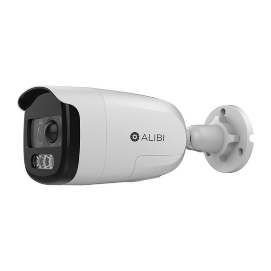
ALI-TP3002LS 2 MP 4-in-1 Bullet
Camera with Strobe and Siren
Quick Installation Guide
The ALIBI ALI-TP3002LS indoor / outdoor bullet camera includes a 4 -in-1 switchable video output (TVI /
AHD / CVI / CVBS) with with an 2 MP sensor and IllumiNite technology for color vision at night. This camera
features:
2 Megapixel (1920 1080 pixels) CMOS sensor up to 30 fps
•
Switchable video output for TVI, AHD, CVI, or CVBS (4 in 1)
•
3.6 mm fixed lens offers horizontal FOV of 83.6°
•
24 hour color image
•
PIR detection, strobe light alarm, alarm out / audible alarm
•
Starlight 2.0 chipset
•
Up to 130 ft white light distance
•
True WDR up to 130 dB
•
IP67 weather-rated with -40°F – 140°F operating temperatures
•
OSD menu (up-the-coax OSD control)
•
Compatible with ALI-AJ1 junction box, ALI-AJ6 junction box
•
Lens
PIR Sensor
White light LED
ALI-TP3002LS camera
12 Vdc power in
Video BNC
connector
Camera drop cable connectors
What's in the box
Box contains:
Installation Guide
•
Drill template
•
Mounting screws and wall inserts
•
What you need
To install the camera, you will need:
12 Vdc power source. See Specifications for requirements.
•
Tools and additional fasteners (may be required) for mounting the camera
•
Video, power and ground (if needed) extension cables
•
Installation
Before installation:
Make sure that the device is in good condition and all the assembly parts are included.
•
Check the specification of the products for the installation environment.
•
Make sure that the wall or the ceiling is strong enough to withstand 4 times the weight of the
•
camera.
www.observint.com
1
Camera body
Mounting base
Lock nut
Adjustable mounting bracket
Cap for switch
cable
Switch
button
Alarm out screw-
down terminals
To avoid fire or shock hazard, use only UL listed power supplies. Verify that the power supply will
•
provide the rated voltage and wattage for the camera. See the Specifications section.
During installation:
Camera Lens: Handle the camera carefully to prevent scratching or soiling the lens. If the lens or IR
•
array shield becomes soiled, clean it only with approved products. See the
Power supply: Camera drop cable: The camera drop cable includes two connectors:
•
Video coax with BNC connector: For transmission of the video signal across a coax (75 Ω)
—
extension cable to a compatible recorder.
Power connector: The camera can be powered by 12 Vdc. When applying 12 Vdc power,
—
observe the power polarity shown on the connector. See the picture to the left for the connector
polarity configuration.
Step 1.
Route interface cables to the camera
Video and power interface cables connect directly to the camera drop cable (see photo above).
The ALI-A6 junction box is compatible with the camera. If using a junction box, connectors between the
camera drop cable and extension cables can be stored within the box,and an earth ground cable can be
used to ground the box and camera.
When selecting a mounting location for the camera
• Make sure that there are no reflective surfaces near to the camera lens. White light from the camera
NOTE
may bounce back onto the lens causing reflections.
• Determine how wiring is routed into the camera. The cable can be routed through an access hole in the
mounting plate, or through the cable in the mounting base.
The camera includes connectors for the following:
Video coax (required): The video drop cable can connect to a video coax extension cable from a
•
Video Recorder or compatible monitor.
12 Vdc power input: Refer to the Specifications section of this document for voltage and current
•
requirements. ALWAYS COMPLY WITH THE POLARITY SHOWN IN THE PICTURE ABOVE.
Alarm output for connection to a reporting device.
•
1.
Route a video coax extension cable from a compatible video recorder (DVR) to where the camera
will be installed.
2.
Route 12 Vdc power extension cables from an adequate power source to the location where the
camera will be installed.
3.
If using a junction box, you can attach an earth ground extension cable to the junction box. Route
the cable to the location of the junction box, if needed. Always follow local electrical codes when
using an earth ground.
4.
If used, route cables from an alarm out device to the camera.
Do not apply power to the camera at this time. Before applying power to the camera, ensure that
the polarity is correct. An incorrect connection may cause a malfunction and can damage the
CAUTION
camera.
Step 2.
Install the camera
The camera can be mounted onto a the ALI-AJ6 junction box, or directly onto a wall or ceiling. The surface
should support at least four times the weight of the camera and junction box (if used). The video / power
drop cable from the camera can be routed either through mounting surface or through a cable channel in
the mounting base.
Installing the camera with a junction box
NOTE: The ALI-AJ1 and ALI-AJ6 junction boxes are very similar.
The ALI-AJ6 junction box is shown below. It can be attached to a wall or ceiling. Video and power
extension cables can be routed in through the opening in the back of the box or through the conduit
coupling, and attached to the camera drop cables inside the box.
section.
Cleaning
ALI-TP3002LS_CQ
191120
Advertisement
Table of Contents

Subscribe to Our Youtube Channel
Related Manuals for ALIBI ALI-TP3002LS


Summary of Contents for ALIBI ALI-TP3002LS
- Page 1 See the section. Cleaning The ALIBI ALI-TP3002LS indoor / outdoor bullet camera includes a 4 -in-1 switchable video output (TVI / Power supply: Camera drop cable: The camera drop cable includes two connectors: •...
- Page 2 Back Front “UP”label Holes for Before applying power to the camera, ensure that the polarity is correct. An incorrect connection mounting can damage the camera. screws (3) CAUTION Holes for mounting Hole for Apply power to the camera. A video image from the camera should appear in the DVR Live View base cable screws (6)
- Page 3 Apply power to the camera. On the camera line, open the drop-down list and select the camera you want to configure. In the example above, the camera connected to channel A1 was selected. Open the DVR Live View screen. Check the Enable box for Motion Detection. Refer to the camera firmware user manual for procedures to configure the motion detection area, setup Motion Detection Alarming Schedule and Step 3.
- Page 4 OSD menu navigation Menu icon For the ALIBI Recorder: Navigation and settings in the OSD are made through direction keys and the Iris + and Iris - buttons in the recorder PTZ Control panel. See below. Click to open OSD menu Direction keys Iris+ Iris–...
- Page 5 WDR (Wide Dynamic Range): DWDR helps the camera provide clear images even under backlight Keys Function circumstances. When both very bright and very dark areas simultaneously exist in the image, WDR Zoom + Zoom in balances the brightness level of the whole image and provides clear images with details. Zoom –...
- Page 6 H: The image flips 180° horizontally. Angle Adjustment Pan: 0 to 360°, Tilt: 0 to 90°, Rotation: 0 to 360° V: The image flips 180° vertically. Menu HV: The image flips 180° both horizontally and vertically. White Light Auto / Off Image Mode STD / HIGH-SAT SMART LIGHT...
Need help?
Do you have a question about the ALI-TP3002LS and is the answer not in the manual?
Questions and answers