Table of Contents
Advertisement
Quick Links
ALI-TP3005L 5MP 4-in-1 Bullet Camera
with IllumiNite Technology
Quick Installation Guide
The ALIBI ALI-TP3005L indoor / outdoor bullet camera includes a 4 -in-1 switchable video output
(TVI / AHD / CVI / CVBS) with a 5MP sensor and IllumiNite technology for color vision at night. This camera
features:
5 Megapixel (2560 × 1944 pixels) progressive scan CMOS sensor up to 20 fps
•
Switchable video output for TVI, AHD, CVI, or CVBS (4-in-1)
•
2.8 mm fixed lens with horizontal FOV of 99.7°
•
Starlight chipset
•
Color: 0.005 Lux, 0 Lux with white light
•
Up to 65 ft white light distance
•
True WDR up to 130 dB
•
IP67 weather-rated with -40°F – 140°F operating temperatures
•
OSD menu (up-the-coax OSD control)
•
Compatible with ALI-AJ1 junction box, ALI-AJ6 junction box
•
Adjustable
Mounting
bracket
Camera
body
White light LED
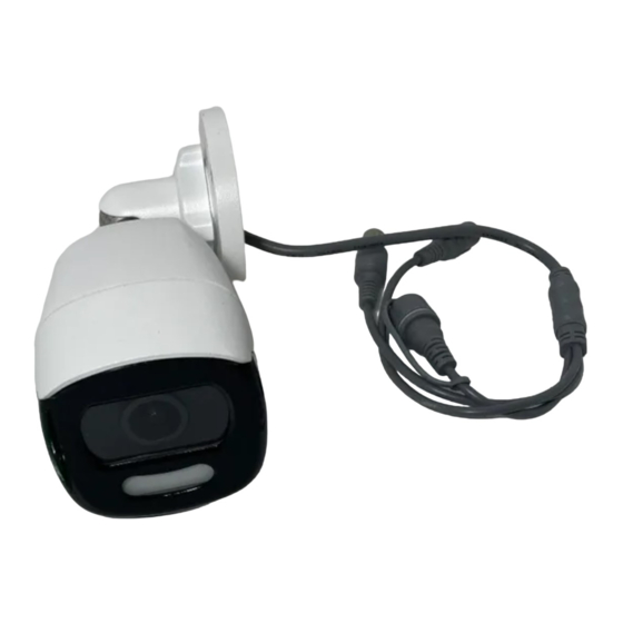
ALI-TP3005L camera
Switch button usage
Camera drop cable connectors
What's in the box
Box contains:
Installation Guide
•
Drill template
•
Mounting screws and wall inserts
•
What you need
To install the camera, you will need:
12 Vdc power source. See Specifications for requirements.
•
Tools and additional fasteners (may be required) for mounting the camera
•
Video, power and ground (if needed) extension cables
•
www.observint.com
1
Mounting
base
HD video BNC connector
Cap for switch cable
Switch
button
12 Vdc power in
Installation
Before installation:
Make sure that the device is in good condition and all the assembly parts are included.
•
Check the specification of the products for the installation environment.
•
Make sure that the wall or the ceiling is strong enough to withstand 4 times the weight of the
•
camera.
To avoid fire or shock hazard, use only UL listed power supplies. Verify that the power supply will
•
provide the rated voltage and wattage for the camera. See the Specifications section.
During installation:
Camera Lens: Handle the camera carefully to prevent scratching or soiling the lens. If the lens or IR
•
array shield becomes soiled, clean it only with approved products. See the
Power supply: Camera drop cable: The camera drop cable includes two connectors:
•
Video coax with BNC connector: For transmission of the video signal across a coax (75 Ω)
—
extension cable to a compatible recorder.
Power connector: The camera can be powered by 12 Vdc. When applying 12 Vdc power,
—
observe the power polarity shown on the connector. See the picture to the left for the connector
polarity configuration.
Ground: A ground cable can be used to ground a junction box. A terminal for an earth ground is
•
provided inside the box. Always ground the box if it is installed in a moist or humid environment.
Follow local electrical codes for proper grounding.
Step 1.
Route interface cables to the camera
Video and power interface cables connect directly to the camera drop cable (see photo above).
The ALI-A6 junction box is compatible with the camera. If using a junction box, connectors between the
camera drop cable and extension cables can be stored within the box,and an earth ground cable can be
used to ground the box and camera.
When selecting a mounting location for the camera
• Make sure that there are no reflective surfaces near to the camera lens. White light from the camera
Lens
NOTE
may bounce back onto the lens causing reflections.
• Determine how wiring is routed into the camera. The cable can be routed through an access hole in the
mounting plate, or through the cable in the mounting base.
The camera includes connectors for the following:
Video coax (required): The video drop cable can connect to a video coax extension cable from a
•
Video Recorder or compatible monitor.
12 Vdc power input: Refer to the Specifications section of this document for voltage and current
•
requirements. ALWAYS COMPLY WITH THE POLARITY SHOWN IN THE PICTURE ABOVE.
1.
Route a video coax extension cable from a compatible video recorder (DVR) to where the camera
will be installed.
2.
Route 12 Vdc power extension cables from an adequate power source to the location where the
camera will be installed.
3.
If using a junction box, you can attach an earth ground extension cable to the junction box. Route
the cable to the location of the junction box, if needed. Always follow local electrical codes when
using an earth ground.
Do not apply power to the camera at this time. Before applying power to the camera, ensure that
the polarity is correct. An incorrect connection may cause a malfunction and can damage the
CAUTION
camera.
Step 2.
Install the camera
The camera can be mounted onto a the ALI-AJ6 junction box, or directly onto a wall or ceiling. The surface
should support at least four times the weight of the camera and junction box (if used). The video / power
drop cable from the camera can be routed either through mounting surface or through a cable channel in
the mounting base.
Installing the camera with a junction box
NOTE: The ALI-AJ1 and ALI-AJ6 junction boxes are very similar.
The ALI-AJ6 junction box is shown below. It can be attached to a wall or ceiling. Video and power
extension cables can be routed in through the opening in the back of the box or through the conduit
coupling, and attached to the camera drop cables inside the box.
section.
ALI-TP3005L_CQ
191203
Advertisement
Table of Contents

Subscribe to Our Youtube Channel
Related Manuals for ALIBI ALI-TP3005L


Summary of Contents for ALIBI ALI-TP3005L
- Page 1 Make sure that the wall or the ceiling is strong enough to withstand 4 times the weight of the • The ALIBI ALI-TP3005L indoor / outdoor bullet camera includes a 4 -in-1 switchable video output camera. (TVI / AHD / CVI / CVBS) with a 5MP sensor and IllumiNite technology for color vision at night. This camera To avoid fire or shock hazard, use only UL listed power supplies.
- Page 2 Front Back “UP”label Holes for Before applying power to the camera, ensure that the polarity is correct. An incorrect connection mounting can damage the camera. screws (3) CAUTION Holes for mounting Hole for base cable screws (6) Apply power to the camera. A video image from the camera should appear in the DVR Live View routing display, or in the Live View display of a remote login to the DVR.
- Page 3 Step 3. Select the video format Menu icon You can set the video format of the camera to either TVI, AHD, CVI, or CVBS. The video format currently selected usually appears in the upper left corner of the Live View screen. The format you select must be compatible with your DVR or monitoring device.
- Page 4 Click the up / down ( p / q ) direction buttons to select the menu item. • For the ALIBI Recorder: Navigation and settings in the OSD are made through direction keys and the Iris Click the left / right ( t / u ) direction buttons to adjust the value of the selected item.
- Page 5 BRIGHTNESS: Brightness refers to the brightness of the image. You can set the brightness value from 1 Frame Rate TVI: 5MP @ 20 fps, 4MP @ 30 fps, 4MP @ 25 fps, 1080p @ 30 fps, 1080p @ 25 fps (dark) to 9 (bright) image.
- Page 6 Troubleshooting Problem Possible Cause Nothing appears on the screen - Check the power connection. - Check the video signal cable connection to the monitor. - Check camera settings to verify the video resolution mode of the camera and recorder match The video image is dim or not clear.
Need help?
Do you have a question about the ALI-TP3005L and is the answer not in the manual?
Questions and answers