Table of Contents
Advertisement
Quick Links
Advertisement
Table of Contents

Related Manuals for ALIBI ALI-TP7112RH


Summary of Contents for ALIBI ALI-TP7112RH
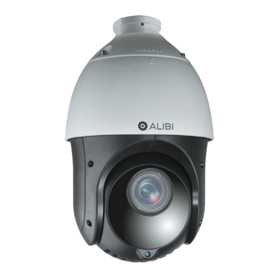
- Page 1 ALI-TP7112RH 1080P 4-in-1 HD IR 25× Zoom Outdoor PTZ Camera User Manual Products: ALI-TP7112RH Please read this manual before using your camera, and always follow the instructions for safety and proper use. Save this manual for future reference. ALI-TP7112RH_CM 190529...
- Page 2 ALIBI and the ALIBI logo are trademarks of Observint. Microsoft, Windows, and Internet Explorer are either registered trademarks or trademarks of Microsoft Corporation in the United States and/or other countries.
- Page 3 If the camera does not work properly, please contact your dealer or the nearest service center. Never attempt to disassemble • the camera yourself. (Your provider is not responsibility for problems caused by unauthorized repair or maintenance.) ALI-TP7112RH PTZ Outdoor Camera User Manual...
- Page 4 SAFETY WARNINGS AND CAUTIONS Cautions Do not drop the dome or subject it to physical shock. Do not expose it to high levels of electromagnetic radiation. • Do not install the camera on surfaces that are subject to vibrations or shock. •...
-
Page 5: Table Of Contents
4.2.2 ALIBI DVR remote access PTZ OSD Main Menu ....... . - Page 6 TABLE OF CONTENTS 4.9.2 Preview a patrol ..............40 4.9.3 Call a patrol .
-
Page 7: Introduction
Introduction The ALIBI™ 4-in-1 HD outdoor PTZ IR camera enables you to pan, tilt and zoom in on suspicious activity and capture high definition video of wide areas such as parking lots, shopping malls and sports facilities. It features a 1/2.8” CMOS image sensor, 25 optical ×... - Page 8 SECTION 1: INTRODUCTION Keyboard Control The pan/tilt/zoom actions of camera can be controlled by the Alibi DVR and the RS-485 interface. Scan Modes The camera provides five scanning modes: pan scanning, tilt scanning, frame scanning, random scanning and panorama scanning.
- Page 9 1-8, pattern 1-4, preset 1-8, panorama scan, tilt scan, day, night, and none. Park Action This feature configures the camera to automatically start a predefined action after a period of inactivity. ALI-TP7112RH PTZ Outdoor Camera User Manual...
-
Page 10: Accessories
SECTION 1: INTRODUCTION 1.2 Accessories The following accessories are available for the ALI-TP7112RH camera. Mounting bracket detail is shown below. Model Type ALI-PTZCL Ceiling Mount Bracket ALI-PTZWB Wall Mount Bracket ALI-PTZPM Pole Mount PTZ Bracket ALI-PTZCM Corner Mount PTZ Bracket ALI-PTZCL: Ceiling Mount Bracket The Ceiling Mount Bracket is suitable for outdoor ceiling mounting. - Page 11 SECTION 1: INTRODUCTION ALI-PTZWB: Wall Mount Bracket The Wall Mount Bracket is suitable for indoor and outdoor wall mounting. 3.82" 12.2" 2.95" G 1.5" 0.33" dia. (4) ALI-TP7112RH PTZ Outdoor Camera User Manual...
- Page 12 SECTION 1: INTRODUCTION ALI-PTZPM: Pole Mount PTZ Bracket The Pole Mount Bracket is suitable for outdoor pole mounting. The straps can attach to a 2.64" ~ 5.00" diameter pole. 3.94" dia. 5.63" 12.2" 4.61" G 1.5"...
- Page 13 SECTION 1: INTRODUCTION ALI-PTZCM: Corner Mount PTZ Bracket 16.52" 6.96" G 1.5" ALI-TP7112RH PTZ Outdoor Camera User Manual...
-
Page 14: Installation
SECTION 2: INSTALLATION SECTION 2 Installation Before you start, check the package contents and make sure that the device in the package is in good condition and all the assembly parts are included. Included are: 24 Vac power supply • Installation tools, bracket adapter •... - Page 15 Loosen the four captive screws on the back of the camera head, and then lift off the maintenance cover. Set DIP switches 1 .. 9 OFF or ON for the device address, buadrate and protocol as preferred using the following tables. DIP switch Device Address ALI-TP7112RH PTZ Outdoor Camera User Manual...
- Page 16 SECTION 2: INSTALLATION DIP switch Device Address If you are installing several RS-485 network devices at the same time, manually setting the DIP switches for address and baud rate will • NOTE help reduce connectivity issues during the initial setup of those devices. By default, the RS-485 line terminator is open (not in use).
-
Page 17: Camera Installation
Drill four screw holes according to the screw holes on the wall mount. Drill a 1-1/4” hole in the mounting surface between the mounting screws appropriate for the camera drop and interface cables. Secure the mounting bracket to the wall with four screws. ALI-TP7112RH PTZ Outdoor Camera User Manual... - Page 18 SECTION 2: INSTALLATION Screws Clip the camera safety cable to the loop on the mounting bracket. Route the camera drop cables through the mounting bracket and through the wall. Fit the coupling at the top of the camera assembly into the end of the mounting bracket (or adapter), and then rotate the camera clockwise about ½...
-
Page 19: Connecting The Cables
Connect the camera ground cable to an earth ground. Follow local electrical codes for specific requirements. Connect the camera HD video drop cable to an HD compatible device, such as an ALIBI HD hybrid video recorder (DVR). Connect the RS-485 drop cables to an RS-485 network if needed. Refer to "APPENDIX B RS-485 Bus Connection" on page 72 for more information. - Page 20 SECTION 2: INSTALLATION Connect the 24 Vac camera cables to a 24 Vac power source. See the Specifications section of power requirements. The power adapter provided is adequate to supply power to the camera. Apply power to the camera. When the camera powers on, an information display appears (see below). (NOTE: The image below shows only the display information.
-
Page 21: Getting Started
(COM FORMAT) are not the same as the settings on RS-485 network, they must be configured to match. Use the features with your control keyboard, DVR, or DVS to configure these parameters. ALI-TP7112RH PTZ Outdoor Camera User Manual... -
Page 22: Basic Operations
SECTION 3: GETTING STARTED 3.1.1 Basic operations You can control the camera using a device such as a RS-485 control keyboard, an ALIBI DVR, or Microsoft Internet Explorer connected t the DVR. Ensure that the communication settings and address for the camera are configured properly in the controlling device. -
Page 23: On Screen Displays
Zone: Display the zone title. • Address: Display the address of the camera. • Error Rate: Display the error rate of the camera. • Fan and Heat: Display the heat information of the camera. • ALI-TP7112RH PTZ Outdoor Camera User Manual... -
Page 24: Configuring The Ptz Camera
Through the PTZ Control panel in the DVR. When using this method, many setup parameters are saved in the DVR. This • method is perhaps the easiest. Specific instructions for using this method are in the ALIBI DVR user manual. -
Page 25: Osd Menu
The menu structure of the on-screen display (OSD) is shown below. You can control the camera directly through the OSD by connecting it to an ALIBI HD capable DVR (DVR) and either using the PTZ Control menu, or by logging into the DVR remotely and using the web interface PTZ control panel. - Page 26 SECTION 4: CONFIGURING THE PTZ CAMERA Click the PTZ Control icon in the Quick Setting Toolbar. The PTZ camera Live View window will expand to full screen and the pop-up window shown below will open. Menu icon In the PTZ Control panel pop-up window, click the Menu icon on the Configuration line.
-
Page 27: Alibi Dvr Remote Access Ptz Osd Main Menu
NOTE configuration options in the camera. 4.2.2 ALIBI DVR remote access PTZ OSD Main Menu To open the PTZ OSD menu during a remote login to the DVR: After logging into the DVR, open the PTZ camera in a single Live View window. - Page 28 SECTION 4: CONFIGURING THE PTZ CAMERA In the PTZ control panel, scroll down the Preset list to Preset95, click the entry to highlight it, and then click the Call icon. See below. The OSD MAIN MENUS screen will open. PTZ control panel Preset95 Call icon The PTZ control panel direction buttons and the Iris + and Iris - keys are used to navigate the OSD menu and set...
-
Page 29: Osd Menu Navigation
SECTION 4: CONFIGURING THE PTZ CAMERA 4.2.3 OSD menu navigation For the ALIBI DVR: Navigation and settings in the OSD are made through direction keys and the Iris + and Iris - buttons in the ALIBI DVR PTZ Control panel. See below. - Page 30 SECTION 4: CONFIGURING THE PTZ CAMERA Position icons For clarity, the video background was removed from most OSD screens shown in the following sections of this document. NOTE Position icons that appear on the OSD menus indicate whether the OSD is in “navigation” mode (for moving throughout the menu system) or “parameter setting”...
-
Page 31: Using The Osd Menu System
Click the p and q direction buttons in the PTZ control panel to cycle through the list of options for the parameter. Click IRIS+ to confirm the change or click IRIS- to cancel and restore the original value. The hollow diamond ( ) mark will revert to the previous icon. ALI-TP7112RH PTZ Outdoor Camera User Manual... -
Page 32: Step 1: Configuring Camera Settings
SECTION 4: CONFIGURING THE PTZ CAMERA 4.4 Step 1: Configuring CAMERA SETTINGS You can set the camera parameters including focus, shutter speed, iris, etc. Configuring image parameters for the camera includes several tasks (see below). The CAMERA PARAMETER submenu include five pages, each with no additional submenu. To open the CAMERA PARAMETERS submenus. - Page 33 GAIN: The value of gain indicates the degree of amplification of the original light signal. You can set the value from 0 to 15. • GAIN LIMIT: You can set this function to limit the gain value. The GAIN LIMIT value ranges from 0 to 15. • ALI-TP7112RH PTZ Outdoor Camera User Manual...
- Page 34 SECTION 4: CONFIGURING THE PTZ CAMERA HLC: High Light Compensation (HLC) masks strong light sources that usually flare across a scene. This makes it possible to see • the detail of the image that would normally be hidden. The value ranges from 0 to 3. INIT LENS: Use INIT LENS to trigger a spontaneous lens initiation for ensuring the normal operation.
-
Page 35: Configure Video Settings
You can create up to 8 privacy masks. To create a masks: Open the PRIVACY submenu from the OSD MAIN MENUS | DOME SETTINGS menu. Click Iris+ to change the MASK NO field. ALI-TP7112RH PTZ Outdoor Camera User Manual... -
Page 36: Step 3: Configuring System Settings
SECTION 4: CONFIGURING THE PTZ CAMERA Use the p and q buttons to change the number shown for the masks number. Privacy masks can be numbered from 1 .. Move the marker to the SET MASK line, and then click IRIS+ to create a mask. Move the position icon to the SET MASK option, and then click Iris+. - Page 37 SOFT BAUDRATE: You can select either 2400, 4800, 9600 or 19200. If the SET SOFT BAUD is set to OFF, the baud rate is set • by the hardware DIP switches. ALI-TP7112RH PTZ Outdoor Camera User Manual...
-
Page 38: Setting System Time
PROTOCOL STATUS: Set PROTOCOL STATUS to ON to enable a user-defined protocol. • PROTOCOL: You can set this option to AUTO MATCH (self adaptive), PELCO-P, PELCO-D, or ALIBI-C. • 485 CHECK: You can set this option to ON or AUTO to improve the PTZ/OSD controls response. ON: detects the protocol, •... -
Page 39: Configuring Display Settings
When calling a preset, the preset number is displayed if both ZOOM SHOW and PT SHOW are enabled. NOTE To use these features: Open the DISPLAY SETTINGS submenu from the OSD MAIN MENUS | DOME SETTINGS (page 1) | SYSTEM SETTINGS (page 2) | DISPLAY SETTINGS menu. ALI-TP7112RH PTZ Outdoor Camera User Manual... -
Page 40: Step 4: Configuring Motion Settings Parameters
SECTION 4: CONFIGURING THE PTZ CAMERA DISPLAY SETTINGS page 1 DISPLAY SETTINGS page 2 Use the p and q buttons to move the position icon to the parameter you want to change, and then click Iris+. The position icon will change to a Use the p and q buttons to show the parameter to what you prefer. -
Page 41: Limit Setting
If you opened LIMIT SETTING, you can configure the scan range limits left, up, right and down. To set stops: Use the p and q buttons to move the position icon to the LIMIT SETTING option, and then click Iris+. ALI-TP7112RH PTZ Outdoor Camera User Manual... - Page 42 SECTION 4: CONFIGURING THE PTZ CAMERA Use the u and the t buttons to move point the camera at the LEFT limit, and then click Iris+ to continue. LIMIT SETTING menus - Left, Up, Right, Down Use the u and the t buttons to move point the camera at the RIGHT limit, and then click Iris+ to continue. Use the p and the q buttons to move point the camera at the UP limit, and then click Iris+ to continue.
-
Page 43: Step 5: Configure Presets
"Table 1. System-defined presets" on page 16. Click IRIS+ to create the preset. Move the position icon to the PRESET PTZ option, and then click Iris+. ALI-TP7112RH PTZ Outdoor Camera User Manual... -
Page 44: Call A Preset
SECTION 4: CONFIGURING THE PTZ CAMERA Use the focus, zoom and iris controls and direction buttons to point the camera at your preset target, then click Iris+ to save the preset and return to the PRESETS menu. Repeat steps 2 through 6 above to create additional presets. 4.8.2 Call a preset Through a web browser connected to your DVR, select the preset number from the preset list in the control panel of the DVR, then click the icon to call the preset. - Page 45 Click the t buttons three times to return to the NUM column, and then click the q to advance to the nest row. Repeat the procedure in steps 6 through 10 above add additional presets to the patrol as needed. ALI-TP7112RH PTZ Outdoor Camera User Manual...
-
Page 46: Preview A Patrol
SECTION 4: CONFIGURING THE PTZ CAMERA Click IRIS+ to save the patrol setup and return to the PATROLS menu. If you call Preset46 to enable the fast patrol, the camera will execute the patrol automatically according to the route configured in preset 1 to preset 32. You can also set the Patrol-D (dwell) time for switching from one preset to another. NOTE Patrol-D can be set to 5S, 10S, 20S, 30S, or 60S. -
Page 47: Create A Pattern
REMAINING (amount of memory remaining) statistic. When REMAINING is “0”, no additional path movements can be saved. Click Iris+ to save the pattern movements and return to the PATTERNS menu. ALI-TP7112RH PTZ Outdoor Camera User Manual... -
Page 48: Preview A Pattern
SECTION 4: CONFIGURING THE PTZ CAMERA 4.10.2 Preview a pattern In the PATTERNS menu, move the position icon to the PATTERN NO option, and then click Iris+. Use the p and q buttons to select the number of the pattern you want to preview, and then click Iris+. Move the position icon to the PREVIEW option, and then click Iris+. - Page 49 Next, click the u button to move the cursor to the START Hours field, and then use the p and q buttons to choose the hour when the task will start. Options are 00 .. 23. ALI-TP7112RH PTZ Outdoor Camera User Manual...
- Page 50 SECTION 4: CONFIGURING THE PTZ CAMERA Next, click the u button to move the cursor to the START Minutes field, and then use the p and q buttons to choose the minute when the task will start. Options are 00 .. 59. Repeat the two previous steps to set the END (H - M) fields (when the task will end).
-
Page 51: Osd Menu Reference
When the OSD opens (see "4.2 Opening the OSD menu" on page 19), the Main Menu appears. The Main Menu provides a gateway to all submenus in the system. 5.1 OSD menu tree The menu structure of the on-screen display (OSD) is shown below. ALI-TP7112RH PTZ Outdoor Camera User Manual... -
Page 52: Sys Info Display
SECTION 5: OSD MENU REFERENCE 5.2 SYS INFO display System information menu displays the current system information of the camera including the camera address, communication parameters, and other parameters. In the SYS INFO displays, these parameters are not changeable, and it is similar to the system information shown when camera is powered on. -
Page 53: Camera Parameter Submenus
Position the marker on the CAMERA PARAMETERS line, and then click the u button in the PTZ control panel repeatedly to open the different displays. To return to the first CAMERA PARAMETERS display, click the t button repeatedly. CAMERA PARAMETERS displays are shown below. Camera Settings page 1 Camera Settings page 2 ALI-TP7112RH PTZ Outdoor Camera User Manual... - Page 54 SECTION 5: OSD MENU REFERENCE Camera Settings page 3 Camera Settings page 4 Camera Settings page 5 Parameter definitions AE mode. AE mode defines the priority of the iris, shutter and gain when the camera adjusts the brightness of the video. The •...
- Page 55 AUTO: In Auto mode, the camera adjusts the color balance according to the current color temperature. — INDOOR, OUTDOOR: These modes are for indoor use and outdoor use respectively. — SELFDEF: In SELFDEF you can adjust the color temperature, the RED and BLUE values, manually. — ALI-TP7112RH PTZ Outdoor Camera User Manual...
-
Page 56: Set Motion Parameters
SECTION 5: OSD MENU REFERENCE ATW: In auto-tracking mode, white balance is adjusted continuously to accord with the color temperature of the scene — illumination. HAUTO: Selecting this mode, the viewed image retains color balance automatically according to the current color —... - Page 57 Use the u and the t buttons to move point the camera at the RIGHT limit, and then click Iris+ to continue. Use the p and the q buttons to move point the camera at the UP limit, and then click Iris+ to continue. ALI-TP7112RH PTZ Outdoor Camera User Manual...
- Page 58 SECTION 5: OSD MENU REFERENCE Use the p and the q buttons to move point the camera at the DOWN limit, and then click Iris+ to continue. Use the p and the q buttons to move position icon to LIMIT STOP, and then click Iris+ to change the setting. Use the p or q buttons switch the LIMIT STOP option to ON, and then click Iris+ to change the setting.
-
Page 59: Patrols Submenu
Click Iris+ to change the PATROL NO field. Use the p and q buttons to change the number shown for the patrol number. Patrols can be numbered from 1 .. 10. Click IRIS+ to create the patrol. ALI-TP7112RH PTZ Outdoor Camera User Manual... - Page 60 SECTION 5: OSD MENU REFERENCE Use the p and q buttons to move the position icon to the EDIT PATROL option, and then click Iris+ to open the edit screen. On the first line (NUM 1) of the edit screen, click the u buttons to move the position icon to the PST (preset) field. Use the p and q buttons to select the first preset of the patrol.
-
Page 61: Patterns Submenu
REMAIN MEMORY indicates the remaining memory of the camera for configuring patterns. When it reaches 0, no more patterns can be • NOTE configured. You can also see the remaining memory shown under PATTERNS menu as REMAINING. Panning/tilting movements and lens operations cannot be memorized simultaneously. • ALI-TP7112RH PTZ Outdoor Camera User Manual... - Page 62 SECTION 5: OSD MENU REFERENCE Click Iris+ to change the PATTERN NO field. Use the p and q buttons to change the number shown for the pattern number. Patterns can be numbered from 1 .. 5. Click IRIS+ to save the pattern. Use the p and q buttons to move the position icon to the EDIT PATTERN option, and then click Iris+ to open the edit screen.
-
Page 63: Presets Submenu
Use the p and q buttons to change the number shown for the preset number. Presets can be numbered from 1 .. 256. Click IRIS+ to create the preset. Move the position icon to the PRESET PTZ option, and then click Iris+. ALI-TP7112RH PTZ Outdoor Camera User Manual... -
Page 64: Privacy Mask Submenu
SECTION 5: OSD MENU REFERENCE Use the focus, zoom and iris controls and direction buttons to point the camera at your preset target, then click Iris+ to save the preset and return to the PRESETS menu. Repeat steps 2 through 6 above to create additional presets. To clear a preset: Open the PRESETS menu, and then select the PRESET NO to clear. -
Page 65: System Settings Submenu
Open the SYSTEM SETTINGS submenu from the OSD MAIN MENUS | DOME SETTINGS (page 1) menu. The SYSTEM SETTINGS submenu includes three pages; you can move between these pages using the u and the t buttons. SYSTEM SETTINGS page 1 SYSTEM SETTINGS page 2 ALI-TP7112RH PTZ Outdoor Camera User Manual... - Page 66 PRESET FOCUS (direct focus): You can set the preset direct focus function to ON or OFF. • Page 3: PROTOCOL STATUS: Set PROTOCOL STATUS to ON to enable a user-defined protocol. • PROTOCOL: You can set this option to AUTO MATCH (self adaptive), PELCO-P, PELCO-D, or ALIBI-C. •...
- Page 67 Repeat the previous step until the current date and time is shown, and then click Iris+ to save the settings and return to the SYSTEM SETTINGS menu. ALI-TP7112RH PTZ Outdoor Camera User Manual...
- Page 68 SECTION 5: OSD MENU REFERENCE Setting DISPLAY SETTINGS The DISPLAY SETTINGS submenu provides options to show several system parameters on the live view display. You can enable or disable the on-screen display of PTZ movements, alarms, time, presets, zone, address, error rate, and fan/heat show, etc. When PT SHOW is set to ON, the camera displays a viewing direction code when you manually rotate the camera.
-
Page 69: Timing Tasks Submenu
PATTERN 1 .. 5, and PRESET 1 .. 8. Click Iris+ to save the task. Use the p and q buttons move the position marker to the TASK TIME option, and then click Iris+. A schedule menu will open. ALI-TP7112RH PTZ Outdoor Camera User Manual... -
Page 70: Video Settings Submenu
SECTION 5: OSD MENU REFERENCE In the schedule menu, use the p and q buttons to choose when, during the week, the task will be executed. Options include WHOLE WEEK, SUNDAY, MONDAY, TUESDAY, WEDNESDAY, THURSDAY, FRIDAY and SATURDAY. Next, click the u button to move the cursor to the START Hours field, and then use the p and q buttons to choose the hour when the task will start. -
Page 71: Zones Submenu
Use the t and u buttons to position the camera to the right extreme of the zone you are configuring, and then click Iris+ to save the settings and return to the ZONES menu. After the zone is defined, the ZONE STATUS changes from OFF to ON. This status is not directly configurable. NOTE ALI-TP7112RH PTZ Outdoor Camera User Manual... -
Page 72: Restore Defaults Option
SECTION 5: OSD MENU REFERENCE To enable scanning of the zone: Use the p and q buttons to move the position marker to the SCAN STATUS option. Click Iris+, and then use the p and q buttons to change the option to ON. Click Iris+ again to save the setting. -
Page 73: Reboot Dome Option
This option is used to change the OSD on screen language. The default language is ENGLISH. To change the OSD language: In the MAIN MENU, use the p and q buttons to move the position icon to LANGUAGE, and then click Iris+. The position icon will change to a ALI-TP7112RH PTZ Outdoor Camera User Manual... -
Page 74: Exit Option
SECTION 5: OSD MENU REFERENCE Use the p or q buttons change the language shown on the parameter line. Options include ENGLISH and CHINESE only. Click Iris+ accept the change, or click Iris– to cancel. 5.8 EXIT option Use this option to close the OSD: In the MAIN MENU, use the p and q buttons to move the position icon at EXIT, and then click Iris+. -
Page 75: Specifications
Focus Auto / Semiautomatic / Manual Horizontal Viewing Angle 57.6° (wide) ~ 2.5° (tele) F-number F1.6 - F3.5 Video Maximum Frame Rate 30 fps @ 1080p Features ALIBI-C UTC 3D Intelligent Positioning Privacy Mask ALI-TP7112RH PTZ Outdoor Camera User Manual... - Page 76 SECTION 6: SPECIFICATIONS Lightening/Surge/Voltage Protection Defog Presets & Patrols 256 presets programmable, 8 patrols, up to 32 presets per patrol, 4 patterns with the total recording time 10 minutes. Interface RS-485 Video Output 1 Vp-p composite output (75 Ω, BNC) HD Video Output 1 Vp-p video output (75 Ω, BNC) General...
-
Page 77: Appendix A Lightning And Surge Protection
45° conical Power arrester envelope The camera should be within a 45° envelope under the lightening rod. The resistance of earthing conductor must be smaller than 4 Ω. Steel jacket Lightning & Surge Protection ALI-TP7112RH PTZ Outdoor Camera User Manual... -
Page 78: Appendix Brs-485 Bus Connection
APPENDIX B: RS-485 BUS CONNECTION APPENDIX B RS-485 Bus Connection General Property of RS-485 Bus RS-485 is a half-duplex communication bus that has a 120 characteristic impedance. The maximum load ability is 32 payloads Ω (including controller device and controlled device). Some bus configurations require a 120 termination at the end of line (see diagrams below). - Page 79 Signal transmission in the star-shaped architecture can be greatly improved by adding an RS-485 distributor. This product effectively changes the star-shape connection to one that satisfies the requirement of the RS-485 industry standard. See the diagram below. ALI-TP7112RH PTZ Outdoor Camera User Manual...
- Page 80 APPENDIX B: RS-485 BUS CONNECTION 120 Ω 120 Ω 120 Ω B– 120 Ω 120 Ω 120 Ω 120 Ω Star-shaped network with an RS-485 Distributor FAQ of RS-485 Bus Fault Probable Cause Solutions The camera will perform a self The address or baud rate is not configured Configure the camera address and baud rate to check but cannot be controlled.
-
Page 81: Appendix C 24 Vac Wire Gauge And Transmission Distance
113 (34) 16 (4) 26 (7) 42 (12) 106 (32) 15 (4) 25 (7) 39 (11) 100 (30) 14 (4) 23 (7) 37 (11) 95 (28) 14 (4) 22 (6) 35 (10) 90 (27) ALI-TP7112RH PTZ Outdoor Camera User Manual... - Page 82 APPENDIX C: 24 VAC WIRE GAUGE AND TRANSMISSION DISTANCE Table 4. Wire Gauge Standards American Wire Gauge Cross-sectional Area of Bare Wire Gauge (mm) Bare Wire (mm 0.750 0.4417 0.800 0.5027 0.900 0.6362 1.000 0.7854 1.250 1.2266 1.500 1.7663 2.000 3.1420 2.500 4.9080...
Need help?
Do you have a question about the ALI-TP7112RH and is the answer not in the manual?
Questions and answers