Table of Contents
Advertisement
Quick Links
www.ti.com
User's Guide
DAC82002EVM User's Guide
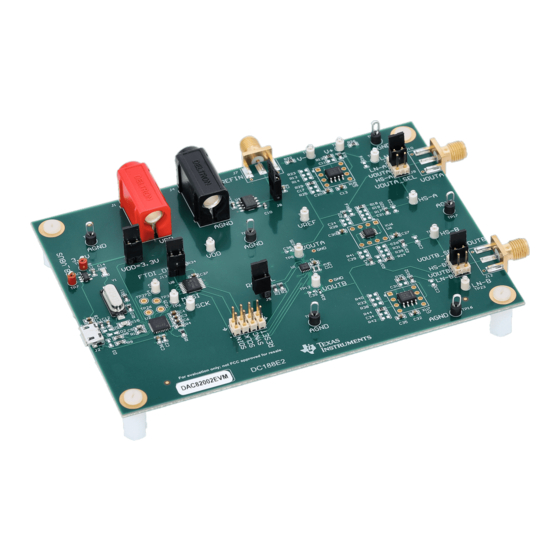
This user's guide describes the characteristics, operation, and use of the DAC82002 evaluation module (EVM).
This EVM is designed to evaluate the performance of the
DAC in a variety of configurations. Throughout this document, the terms evaluation board, evaluation module,
and EVM are synonymous with the DAC82002EVM. This document includes a schematic, printed-circuit board
(PCB) layouts, and a complete bill of materials.
SBAU401 – AUGUST 2022
Submit Document Feedback
ABSTRACT
DAC82002
Copyright © 2022 Texas Instruments Incorporated
commercial, unbuffered voltage output
DAC82002EVM User's Guide
1
Advertisement
Table of Contents

Related Manuals for Texas Instruments DAC82002EVM


Summary of Contents for Texas Instruments DAC82002EVM
- Page 1 DAC in a variety of configurations. Throughout this document, the terms evaluation board, evaluation module, and EVM are synonymous with the DAC82002EVM. This document includes a schematic, printed-circuit board (PCB) layouts, and a complete bill of materials.
-
Page 2: Table Of Contents
Figure 2-1. Software Installation Path............................4 Figure 2-2. FTDI USB Drivers..............................5 Figure 2-3. Hardware Setup................................ Figure 3-1. DAC82002EVM Hardware Simplified Schematic...................... Figure 3-2. Default Buffer Configuration............................Figure 3-3. Buffer DIP Adapter Connections..........................Figure 3-4. DAC82002EVM GUI Location........................... Figure 3-5. DAC82002EVM GUI Connection Detection...................... -
Page 3: Overview
The following document provides information regarding Texas Instruments integrated circuits used in the assembly of the DAC82002EVM. This user's guide is available from the TI web site under literature number SBAU401. Any letter appended to the literature number corresponds to the document revision that is current at the time of the writing of this document. -
Page 4: System Setup
™ 7 and 10 operating systems. 2.1.2 Software Installation Before installing the software, make sure that the DAC82002EVM is not connected to the local machine. Download the software from DAC82002EVM tool folder. After the software is downloaded, navigate to the download folder, and run the DAC82002EVM software installer executable file. -
Page 5: Figure 2-2. Ftdi Usb Drivers
Figure 2-2 shows the FTDI USB drivers installation window that is automatically launched after the DAC82002EVM software installation is complete. Figure 2-2. FTDI USB Drivers SBAU401 – AUGUST 2022 DAC82002EVM User's Guide Submit Document Feedback Copyright ©... -
Page 6: Hardware Setup
AGND VREFIN 2 V to VDD; ignore if J8 is shorted and onboard 2.5-V VREF is used The jumper settings on the DAC82002EVM are crucial to the proper operation of the EVM. Table 2-2 provides the details of the configurable jumper settings on the EVM. -
Page 7: Detailed Description
The following sections provide detailed information on the EVM hardware and jumper configuration settings. 3.1.1 Theory of Operation Figure 3-1 shows a simplified schematic of the DAC82002EVM board. By default, the DAC82002EVM features OPA388 single-channel, low-noise operational amplifiers, and one... -
Page 8: Figure 3-2. Default Buffer Configuration
3.1.1.2 Buffer Customization The DAC82002EVM has three operational amplifier circuits that can be configured using 0-Ω resistors. All three circuits act as unity gain buffers with the default resistor placement. The following figure shows the 0-Ω resistors are the only resistors that are populated on the DAC82002EVM by default. -
Page 9: Software Description
Detailed Description 3.2 Software Description This section describes the features of the DAC82002EVM software, and discusses how to use these features. The software provides basic control of all the DAC82002 registers and functions. 3.2.1 Starting the Software To launch the software, locate the Texas Instruments folder in the All Programs menu, and select the DAC82002EVM icon. -
Page 10: Figure 3-6. Low Level Configuration Page
Write Modified • Read Selected • Read All The DAC82002EVM only supports writing to the device registers, so Read Selected and Read All have no effect. Figure 3-7. Low Level Configuration Page Options DAC82002EVM User's Guide SBAU401 – AUGUST 2022 Submit Document Feedback Copyright ©... -
Page 11: Schematic, Pcb Layout, And Bill Of Materials
Schematic, PCB Layout, and Bill of Materials 4 Schematic, PCB Layout, and Bill of Materials This section contains the schematics, printed circuit board (PCB) layout diagrams, and a complete bill of materials for the DAC82002EVM. 4.1 Schematic USB_VBUS SCK_ISO VCCIN 3.3V_PS... -
Page 12: Figure 4-2. Dac82002Evm Schematic
Schematic, PCB Layout, and Bill of Materials www.ti.com Figure 4-2. DAC82002EVM Schematic Page 2 DAC82002EVM User's Guide SBAU401 – AUGUST 2022 Submit Document Feedback Copyright © 2022 Texas Instruments Incorporated... -
Page 13: Figure 4-3. Dac82002Evm Schematic
VREF AGND HS-B LN-B VOUTB VOUTB HS-B OPA388IDR LN-B TP21 OPA2328DGKR TP23 AGND AGND AGND AGND 100nF AGND Figure 4-3. DAC82002EVM Schematic Page 3 SBAU401 – AUGUST 2022 DAC82002EVM User's Guide Submit Document Feedback Copyright © 2022 Texas Instruments Incorporated... -
Page 14: Pcb Layout
Schematic, PCB Layout, and Bill of Materials www.ti.com 4.2 PCB Layout Figure 4-4. DAC82002EVM PCB Components Layout DAC82002EVM User's Guide SBAU401 – AUGUST 2022 Submit Document Feedback Copyright © 2022 Texas Instruments Incorporated... -
Page 15: Figure 4-5. Dac82002Evm Pcb Layers
Schematic, PCB Layout, and Bill of Materials Figure 4-5. DAC82002EVM PCB Layers SBAU401 – AUGUST 2022 DAC82002EVM User's Guide Submit Document Feedback Copyright © 2022 Texas Instruments Incorporated... -
Page 16: Bill Of Materials
Schematic, PCB Layout, and Bill of Materials www.ti.com 4.3 Bill of Materials Table 4-1. DAC82002EVM Bill of Materials Designator Quantity Value Description Package Reference Part Number Manufacturer !PCB Printed circuit board DC188 C1, C2, C3, C8, C9, C12, C13, CAP, CERM, 0.1 µF, 50 V,±10%, X7R, AEC- C20, C22, C27, C30, C32, C35, 0.1 µF... - Page 17 Schematic, PCB Layout, and Bill of Materials Table 4-1. DAC82002EVM Bill of Materials (continued) Designator Quantity Value Description Package Reference Part Number Manufacturer 600 Ω Ferrite bead, 600 Ω at 100 MHz, 1 A, 0603 782633601 Wurth Elektronik Thermal transfer printable labels, 0.650" W PCB label 0.650 ×...
- Page 18 Schematic, PCB Layout, and Bill of Materials www.ti.com Table 4-1. DAC82002EVM Bill of Materials (continued) Designator Quantity Value Description Package Reference Part Number Manufacturer Single power supply, quadruple buffer gate with 3-state output CMOS logic level shifter, PW0014A SN74LV4T125PWR Texas Instruments PW0014A, large T and R Socket, DIP-8, 2.54-mm...
- Page 19 STANDARD TERMS FOR EVALUATION MODULES Delivery: TI delivers TI evaluation boards, kits, or modules, including any accompanying demonstration software, components, and/or documentation which may be provided together or separately (collectively, an “EVM” or “EVMs”) to the User (“User”) in accordance with the terms set forth herein.
- Page 20 www.ti.com Regulatory Notices: 3.1 United States 3.1.1 Notice applicable to EVMs not FCC-Approved: FCC NOTICE: This kit is designed to allow product developers to evaluate electronic components, circuitry, or software associated with the kit to determine whether to incorporate such items in a finished product and software developers to write software applications for use with the end product.
- Page 21 www.ti.com Concernant les EVMs avec antennes détachables Conformément à la réglementation d'Industrie Canada, le présent émetteur radio peut fonctionner avec une antenne d'un type et d'un gain maximal (ou inférieur) approuvé pour l'émetteur par Industrie Canada. Dans le but de réduire les risques de brouillage radioélectrique à...
- Page 22 www.ti.com EVM Use Restrictions and Warnings: 4.1 EVMS ARE NOT FOR USE IN FUNCTIONAL SAFETY AND/OR SAFETY CRITICAL EVALUATIONS, INCLUDING BUT NOT LIMITED TO EVALUATIONS OF LIFE SUPPORT APPLICATIONS. 4.2 User must read and apply the user guide and other available documentation provided by TI regarding the EVM prior to handling or using the EVM, including without limitation any warning or restriction notices.
- Page 23 Notwithstanding the foregoing, any judgment may be enforced in any United States or foreign court, and TI may seek injunctive relief in any United States or foreign court. Mailing Address: Texas Instruments, Post Office Box 655303, Dallas, Texas 75265 Copyright © 2019, Texas Instruments Incorporated...
- Page 24 TI products. TI’s provision of these resources does not expand or otherwise alter TI’s applicable warranties or warranty disclaimers for TI products. TI objects to and rejects any additional or different terms you may have proposed. IMPORTANT NOTICE Mailing Address: Texas Instruments, Post Office Box 655303, Dallas, Texas 75265 Copyright © 2022, Texas Instruments Incorporated...
Need help?
Do you have a question about the DAC82002EVM and is the answer not in the manual?
Questions and answers