Table of Contents
Advertisement
Quick Links
www.ti.com
EVM User's Guide: DAC80502-01EVM
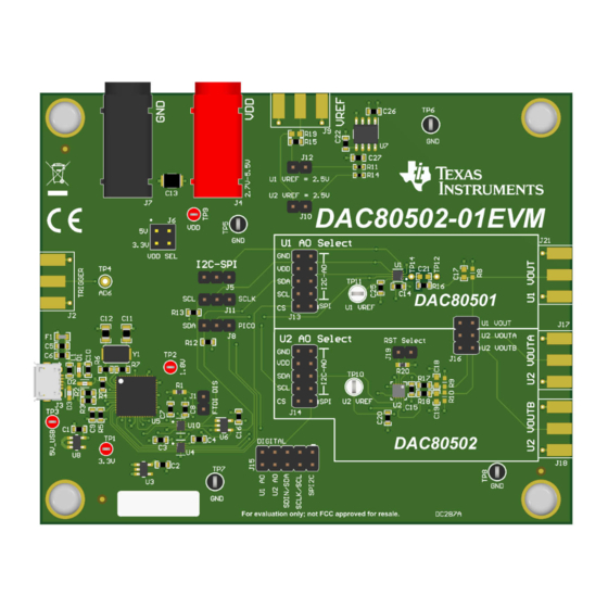
DAC80502-01 Evaluation Module
Description
The
DAC80502-01EVM
is an easy-to-use platform
to evaluate the functionality and performance
of the
DAC80502
and
DAC80501
DAC80502-01EVM has optional circuits and jumpers
to configure the device for different applications. The
DAC80502 and DAC80501 are both installed on the
EVM.
DAC80501 is a single-channel, buffered, low-voltage-
output digital-to-analog converter (DAC) in 16-bit
resolution. DAC80502 is a dual-channel, buffered,
low-voltage-output DAC in 16-bit resolution. The
devices provide unipolar output voltage up to 5 V.
Get Started
1. Order the EVM.
2. Configure EVM jumpers.
3. Install the DAC805xxEVM GUI from ti.com.
4. Connect USB and external power supplies.
5. Launch the DAC805xxEVM GUI.
SLAU919 – NOVEMBER 2023
Submit Document Feedback
Features
•
devices. The
•
•
•
•
•
Applications
•
•
•
•
•
•
•
•
Copyright © 2023 Texas Instruments Incorporated
Configurable circuit to evaluate the DACx0501 and
DACx0502 family of devices
Onboard VDD (5-V or 3.3-V) support via USB and
on-board voltage regulators
FT4232 easily writes to the DAC using the
DAC805xxEVM GUI
Option for external reference voltage or on-board
2.5-V reference voltage
Trigger output is available for synchronous
measurement
2
External SPI and I
C connections available
Oscilloscopes and digitizers
Parametric measurement unit (PMU)
Data acquisition (DAQ)
Flat panel display (FPD) shorting bar pattern
generator
Small cell base station
Analog output module
Process analytics (pH, gas, concentration, force
and humidity)
Programmable dc power supply
DAC80502-01 Evaluation Module
Description
1
Advertisement
Table of Contents

Related Manuals for Texas Instruments DAC80502-01


Summary of Contents for Texas Instruments DAC80502-01
- Page 1 Small cell base station 5. Launch the DAC805xxEVM GUI. • Analog output module • Process analytics (pH, gas, concentration, force and humidity) • Programmable dc power supply SLAU919 – NOVEMBER 2023 DAC80502-01 Evaluation Module Submit Document Feedback Copyright © 2023 Texas Instruments Incorporated...
-
Page 2: Kit Contents
This document focuses on the DAC80501 and DAC80502 that come pre-installed on the EVM. Table 1-2. DAC80502-01EVM Supported Devices DACx050x DAC Resolution Number of DACs DAC60501 12-bit DAC70501 14-bit DAC80501 16-bit DAC60502 12-bit DAC70502 14-bit DAC80502 16-bit DAC80502-01 Evaluation Module SLAU919 – NOVEMBER 2023 Submit Document Feedback Copyright © 2023 Texas Instruments Incorporated... - Page 3 VREFIO pin. Each of the DAC outputs have footprints available for capacitor and resistor loads that are unpopulated by default. SLAU919 – NOVEMBER 2023 DAC80502-01 Evaluation Module Submit Document Feedback Copyright © 2023 Texas Instruments Incorporated...
-
Page 4: Jumper Definitions
OPEN – Open if external communication is used. SHORT 1-2 – DAC80502 RSTSEL pin is connected to VDD. RST Select OPEN – DAC80502 RSTSEL pin is connected to GND (default). DAC80502-01 Evaluation Module SLAU919 – NOVEMBER 2023 Submit Document Feedback Copyright © 2023 Texas Instruments Incorporated... -
Page 5: Connector Definitions
The DAC references are connected to this SMA by resistors R15 (DAC80501) and R19 (DAC80502) To avoid shorting the two references together, R19 is unpopulated by default SLAU919 – NOVEMBER 2023 DAC80502-01 Evaluation Module Submit Document Feedback Copyright © 2023 Texas Instruments Incorporated... -
Page 6: Test Points
DAC80501 reference test point TP12 Dedicated ground test point for measuring VOUT noise Dedicated DAC80501 VOUT test point for measuring VOUT TP14 VOUT noise DAC80502-01 Evaluation Module SLAU919 – NOVEMBER 2023 Submit Document Feedback Copyright © 2023 Texas Instruments Incorporated... -
Page 7: Hardware Overview
DAC80501 SYNC/A0 1, 3, 5, 7, 9 Ground 2.2.3 SPI Configuration Figure 2-3 shows the DAC80502-01EVM configured for SPI communication. Figure 2-3. DAC80502-01EVM SPI Configuration SLAU919 – NOVEMBER 2023 DAC80502-01 Evaluation Module Submit Document Feedback Copyright © 2023 Texas Instruments Incorporated... - Page 8 A0 jumpers for specific device addresses. Table 2-7. I C Device Address Map A0 Connection [A6:A0] 1001 000 1001 001 1001 010 1001 011 DAC80502-01 Evaluation Module SLAU919 – NOVEMBER 2023 Submit Document Feedback Copyright © 2023 Texas Instruments Incorporated...
-
Page 9: Software Installation
When the DAC805xx GUI is launched, an installation dialog window opens and prompts the user to select an installation directory. If left unchanged, Figure 3-1 shows that the software location defaults to C:\Program Files (x86)\Texas Instruments\DAC805xxEVM. Figure 3-1. Software Installation Path SLAU919 – NOVEMBER 2023 DAC80502-01 Evaluation Module Submit Document Feedback Copyright © 2023 Texas Instruments Incorporated... - Page 10 Figure 3-2 shows the FTDI USB drivers installation window that is automatically launched after the DAC805xx software installation is complete. Figure 3-2. FTDI USB Drivers DAC80502-01 Evaluation Module SLAU919 – NOVEMBER 2023 Submit Document Feedback Copyright © 2023 Texas Instruments Incorporated...
-
Page 11: Software Overview
I C address. Select the CONFIG button to save the current settings and launch the main GUI. Figure 3-4. DAC8050xxEVM Interface Settings Menu SLAU919 – NOVEMBER 2023 DAC80502-01 Evaluation Module Submit Document Feedback Copyright © 2023 Texas Instruments Incorporated... - Page 12 GUI after launch with the DAC80501 register map loaded. Figure 3-6 shows the GUI after launch with the DAC80502 register map loaded. Figure 3-5. DAC805xxEVM GUI DAC80501 Selection at Launch DAC80502-01 Evaluation Module SLAU919 – NOVEMBER 2023 Submit Document Feedback Copyright © 2023 Texas Instruments Incorporated...
- Page 13 DEMO MODE or CONNECTED. After the FTDI controller is properly connected to the computer, restart the DAC805xxEVM software to detect the device. Figure 3-7. FTDI Digital Controller Connection Status SLAU919 – NOVEMBER 2023 DAC80502-01 Evaluation Module Submit Document Feedback Copyright © 2023 Texas Instruments Incorporated...
- Page 14 Data are written to the registers by entering a value in the value column of the GUI. Figure 3-8. DAC80501 Low Level Configuration Page DAC80502-01 Evaluation Module SLAU919 – NOVEMBER 2023 Submit Document Feedback Copyright © 2023 Texas Instruments Incorporated...
- Page 15 Software Figure 3-9. DAC80502 Low Level Configuration Page SLAU919 – NOVEMBER 2023 DAC80502-01 Evaluation Module Submit Document Feedback Copyright © 2023 Texas Instruments Incorporated...
- Page 16 DAC. The internal reference and the reference division can also be powered on and off here. Figure 3-10. DAC80501 Tab of the High Level Configuration Page DAC80502-01 Evaluation Module SLAU919 – NOVEMBER 2023 Submit Document Feedback Copyright © 2023 Texas Instruments Incorporated...
- Page 17 DACs. The internal reference and the reference division can also be powered on and off here. Figure 3-11. DAC80502 Tab of the High Level Configuration Page SLAU919 – NOVEMBER 2023 DAC80502-01 Evaluation Module Submit Document Feedback Copyright © 2023 Texas Instruments Incorporated...
- Page 18 SPI2C SPI2C AGND DUT_CS_2 SYNC_A1 RST Select DUT_CS_2 DAC80502DRX SH10 U2 A0 Select SPI2C SCLK_SCL SDIN_SDA SYNC_A1 SYNC_A0 DIGITAL Figure 4-2. DAC80502-01EVM DUT Schematic DAC80502-01 Evaluation Module SLAU919 – NOVEMBER 2023 Submit Document Feedback Copyright © 2023 Texas Instruments Incorporated...
- Page 19 DAC80502-01EVM. Figure 4-3. DAC80502-01EVM PCB Top Layer Layout Figure 4-4. DAC80502-01EVM PCB Mid Layer 1 Layout (Ground Plane) SLAU919 – NOVEMBER 2023 DAC80502-01 Evaluation Module Submit Document Feedback Copyright © 2023 Texas Instruments Incorporated...
- Page 20 Hardware Design Files www.ti.com Figure 4-5. DAC80502-01EVM PCB Mid Layer 2 Layout (Power Plane) Figure 4-6. DAC80502-01EVM PCB Bottom Layer Layout DAC80502-01 Evaluation Module SLAU919 – NOVEMBER 2023 Submit Document Feedback Copyright © 2023 Texas Instruments Incorporated...
-
Page 21: Bill Of Materials
Header, 2.54mm, 3x2, Gold, Header, 2.54mm, 61300621121 Wurth Elektronik 3x2, TH Ferrite Bead, 600 Ω @ 100 600 Ω 0603 782633601 Wurth Elektronik MHz, 1 A, 0603 SLAU919 – NOVEMBER 2023 DAC80502-01 Evaluation Module Submit Document Feedback Copyright © 2023 Texas Instruments Incorporated... - Page 22 1.8 to 5.5 V Input, with Low DBV0005A TPS72118DBVR Texas Instruments IQ, 5-pin SOT-23 (DBV), -40 to 125 degC, Green (RoHS & no Sb/Br) DAC80502-01 Evaluation Module SLAU919 – NOVEMBER 2023 Submit Document Feedback Copyright © 2023 Texas Instruments Incorporated...
- Page 23 J2, J9, J17, J18, Connector, End launch SMA, End Launch SMA 142-0701-801 Cinch Connectivity 50 Ω, SMT R8, R9, R10 0603 0 Ω 0603 SLAU919 – NOVEMBER 2023 DAC80502-01 Evaluation Module Submit Document Feedback Copyright © 2023 Texas Instruments Incorporated...
-
Page 24: Related Documentation
Newer revisions are available from the TI web site at www.ti.com, or call the Texas Instruments Literature Response Center at (800) 477-8924 or the Product Information Center at (972) 644-5580. When ordering, identify the document by both title and literature number. - Page 25 STANDARD TERMS FOR EVALUATION MODULES Delivery: TI delivers TI evaluation boards, kits, or modules, including any accompanying demonstration software, components, and/or documentation which may be provided together or separately (collectively, an “EVM” or “EVMs”) to the User (“User”) in accordance with the terms set forth herein.
- Page 26 www.ti.com Regulatory Notices: 3.1 United States 3.1.1 Notice applicable to EVMs not FCC-Approved: FCC NOTICE: This kit is designed to allow product developers to evaluate electronic components, circuitry, or software associated with the kit to determine whether to incorporate such items in a finished product and software developers to write software applications for use with the end product.
- Page 27 www.ti.com Concernant les EVMs avec antennes détachables Conformément à la réglementation d'Industrie Canada, le présent émetteur radio peut fonctionner avec une antenne d'un type et d'un gain maximal (ou inférieur) approuvé pour l'émetteur par Industrie Canada. Dans le but de réduire les risques de brouillage radioélectrique à...
- Page 28 www.ti.com EVM Use Restrictions and Warnings: 4.1 EVMS ARE NOT FOR USE IN FUNCTIONAL SAFETY AND/OR SAFETY CRITICAL EVALUATIONS, INCLUDING BUT NOT LIMITED TO EVALUATIONS OF LIFE SUPPORT APPLICATIONS. 4.2 User must read and apply the user guide and other available documentation provided by TI regarding the EVM prior to handling or using the EVM, including without limitation any warning or restriction notices.
- Page 29 Notwithstanding the foregoing, any judgment may be enforced in any United States or foreign court, and TI may seek injunctive relief in any United States or foreign court. Mailing Address: Texas Instruments, Post Office Box 655303, Dallas, Texas 75265 Copyright © 2023, Texas Instruments Incorporated...
-
Page 30: Important Notice
TI products. TI’s provision of these resources does not expand or otherwise alter TI’s applicable warranties or warranty disclaimers for TI products. TI objects to and rejects any additional or different terms you may have proposed. IMPORTANT NOTICE Mailing Address: Texas Instruments, Post Office Box 655303, Dallas, Texas 75265 Copyright © 2023, Texas Instruments Incorporated...
Need help?
Do you have a question about the DAC80502-01 and is the answer not in the manual?
Questions and answers