Table of Contents
Advertisement
Quick Links
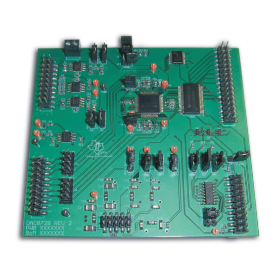
This user's guide describes the characteristics, operation, and use of the DAC8728EVM, an evaluation
board for the DAC8728. The DAC8728 is a low-power, octal, ±15V output, parallel input, 16-bit
digital-to-analog converter (DAC). This evaluation module (EVM) allows evaluation of all aspects of the
DAC8728 and gives control over every pin on the device. Complete circuit descriptions, schematic
diagrams, and bills of material are included in this document.
The following related documents are available through the Texas Instruments web site at www.ti.com.
All trademarks are the property of their respective owners.
SBAU161 – February 2010
Submit Documentation Feedback
DAC8728EVM
Related Documentation
Device
DAC8728
OPA277
REF5050
REF02
SN74LVC16245A
SN74LVC139
SN74LVC374A
5-6k Interface Board
DAP Signal Conditioning Board
Copyright © 2010, Texas Instruments Incorporated
DAC8728EVM
Literature Number
SBAS466
SBOS079A
SBOS410C
SBVS003B
SCES062O
SCAS341O
SCAS296N
SLAU104
SLAU105
User's Guide
SBAU161 – February 2010
1
DAC8728EVM
Advertisement
Table of Contents

Subscribe to Our Youtube Channel
Related Manuals for Texas Instruments DAC8728EVM


Summary of Contents for Texas Instruments DAC8728EVM
- Page 1 DAC8728EVM DAC8728EVM This user's guide describes the characteristics, operation, and use of the DAC8728EVM, an evaluation board for the DAC8728. The DAC8728 is a low-power, octal, ±15V output, parallel input, 16-bit digital-to-analog converter (DAC). This evaluation module (EVM) allows evaluation of all aspects of the DAC8728 and gives control over every pin on the device.
-
Page 2: Table Of Contents
A2 and A3 Address Combinations ................Commonly-Used Address Combinations .................. J4 Configuration: Power-Supply Input ................. DAC8718EVM Factory Default Configuration ................... Unipolar/Single-Supply Configuration ..................Bipolar/Dual-Supply Configuration ..................DAC8728EVM Bill of Materials DAC8728EVM SBAU161 – February 2010 Submit Documentation Feedback Copyright © 2010, Texas Instruments Incorporated... -
Page 3: Evm Overview
Pins are unused and should be left open for use with future J5.18 - J5.20 Unused amplifier and sensor input modules. J1.1- J1.19 (odd) AGND Analog ground connections SBAU161 – February 2010 DAC8728EVM Submit Documentation Feedback Copyright © 2010, Texas Instruments Incorporated... -
Page 4: Digital Interface
TP9 and is connected to a 0.1mF capacitor. Digital Interface The DAC8728EVM is designed for easy interfacing to multiple control platforms. To achieve this host processor flexibility, an unconventional way of controlling this EVM had to be developed. Therefore, the 16-bit data bus from the host processor is shared between the 16-bit data bus and the 5-bit A0–A4... -
Page 5: Parallel Control
J2.13 EVM_A3 with U8 to control DC_CS and LDAC J2.15 Unused — J2.17 Unused — DSP Interrupt Input: Connects to BUSY J2.19 output of the DAC8728 SBAU161 – February 2010 DAC8728EVM Submit Documentation Feedback Copyright © 2010, Texas Instruments Incorporated... -
Page 6: Parallel Control Header And Sn74Lvc139
As you can see from the timing diagram, the CS line never goes low unless the DC_CS signal and either WE or RE is low as well. Table 3. External Logic Behavior DC_CS Not a valid DSP output DAC8728EVM SBAU161 – February 2010 Submit Documentation Feedback Copyright © 2010, Texas Instruments Incorporated... -
Page 7: Latch External Logic
EXT_LDAC signal and then waits for the next interrupt. Table 5 displays the behavior of the logic. Table 5. LDAC Control EXT_LDAC LDAC_CTRL LDAC SBAU161 – February 2010 DAC8728EVM Submit Documentation Feedback Copyright © 2010, Texas Instruments Incorporated... - Page 8 DAC8728. The gain registers and zero registers are loaded with the respective default values and the communication bus is disabled. For normal operation, the RST signal must remain high. DAC8728EVM SBAU161 – February 2010 Submit Documentation Feedback Copyright © 2010, Texas Instruments Incorporated...
-
Page 9: A0 And A1 Address Combinations
The BUSY pin is pulled low when the correction engine runs, and is pulled high by an external pull-up when the correction process completes. SBAU161 – February 2010 DAC8728EVM Submit Documentation Feedback Copyright © 2010, Texas Instruments Incorporated... -
Page 10: Shared 16-Bit Parallel Bus
4.11 Parallel Data The DAC8728EVM uses Samtec part numbers SSW-116-22-S-D-VS and TSM-116-01-T-DV to provide a convenient, 16-pin, dual row header/socket combination at J6. This header/socket combination provides access to the parallel data pins of the DAC8728 and the inputs to the SN74LVC374. Data lines D0 to D15 are located on the odd numbered pins 1 through 31 on the J6 header. -
Page 11: Power Supplies
NOTE: To avoid damage to the DAC8728, DV must stay greater than or equal to IOV The DAC8728EVM board analog section can be powered from either a single-supply or dual supply. In unipolar mode, AV is tied to AGND and AV is powered from +VA, a +8 to +36V analog supply range. -
Page 12: Reference Voltage
3-state mode. Digital Control The digital control signals can be applied directly to J1 (top or bottom side). The DAC8728EVM can also be connected directly to a DSP or microcontroller interface board. No specific evaluation software is provided with this EVM; however, various code examples are available that show how to use this EVM with a variety of digital signal processors from Texas Instruments. -
Page 13: Dac8718Evm Factory Default Configuration
Once the EVM is powered, the user can apply the appropriate parallel data and control signals to the EVM using J1 and J6. The DAC8728EVM can also be connected directly to the 5-6k Interface Board for use with a variety of C5000 and C6000 series DSP Starter Kits (DSKs), available from Texas Instruments. The parallel control and data connectors are designed to allow pattern generators and/or logic analyzers to be connected to the EVM using standard ribbon type cables on 0.1”... -
Page 14: Dac8728Evm Unipolar/Single-Supply Setup
JP3, JP4, JP5, JP6, JP7, JP9, JP15, JP17, JP19, JP20 JP14 JP1, JP2, JP18 Open JP8, JP16, JP11, JP13 Closed JP10 Figure 5. DAC8728EVM Unipolar/Single-Supply Setup DAC8728EVM SBAU161 – February 2010 Submit Documentation Feedback Copyright © 2010, Texas Instruments Incorporated... -
Page 15: Bipolar/Dual-Supply Configuration
Position JP3, JP4, JP5, JP6, JP7, JP9, JP14, JP15, JP17, JP19, JP20, JP1, JP2, JP8, JP13, JP16, JP18 Open JP11 Closed JP10 Figure 6. Bipolar/Dual-Supply Configuration SBAU161 – February 2010 DAC8728EVM Submit Documentation Feedback Copyright © 2010, Texas Instruments Incorporated... -
Page 16: Schematics And Layout
Schematics and Layout www.ti.com Schematics and Layout Schematics for the DAC8728EVM are appended to this user's guide. The bill of materials is provided in Table Bill of Materials NOTE: All components should be compliant with the European Union Restriction on Use of Hazardous Substances (RoHS) Directive. - Page 17 Schematics and Layout www.ti.com Table 13. DAC8728EVM Bill of Materials (continued) Item No. Ref Des Description Manufacturer Mfr Part Number TP1-TP4, TP6 - Test Point: sSingle .025 Pin, Red Keystone 5000 TP12, TP15-TP18 TP5, TP13, TP14 Test Point: single .025 Pin, Black...
- Page 18 IOVDD IOVDD IOVDD R2 49.9 LATCH_CTRL DC_/CS AVDD AVDD LATCH 0.01uF Vout SN74LVC1G08 AVDD SN74LVC1G32 SN74LVC1G32 AND Gate OR Gate TEMP TRIM 0.1uF OR Gate 22uF 47uF 0.01uF VOUT_3 OPA_Out1 REF02 0.1uF VOUT_2 -InA VOUT_1 OutA VOUT_0 +InA REF5V REF5V OP-AMP1 OPA_Out2 +InB...
- Page 19 Evaluation Board/Kit Important Notice Texas Instruments (TI) provides the enclosed product(s) under the following conditions: This evaluation board/kit is intended for use for ENGINEERING DEVELOPMENT, DEMONSTRATION, OR EVALUATION PURPOSES ONLY and is not considered by TI to be a finished end-product fit for general consumer use. Persons handling the product(s) must have electronics training and observe good engineering practice standards.
- Page 20 IMPORTANT NOTICE Texas Instruments Incorporated and its subsidiaries (TI) reserve the right to make corrections, modifications, enhancements, improvements, and other changes to its products and services at any time and to discontinue any product or service without notice. Customers should obtain the latest relevant information before placing orders and should verify that such information is current and complete.
- Page 21 Компания «ЭлектроПласт» предлагает заключение долгосрочных отношений при поставках импортных электронных компонентов на взаимовыгодных условиях! Наши преимущества: Оперативные поставки широкого спектра электронных компонентов отечественного и импортного производства напрямую от производителей и с крупнейших мировых складов; Поставка более 17-ти миллионов наименований электронных компонентов; ...
Need help?
Do you have a question about the DAC8728EVM and is the answer not in the manual?
Questions and answers