Table of Contents
Advertisement
Quick Links
This user's guide describes the characteristics, operation, and use of the DAC81416 evaluation module
(EVM). This document also discusses the proper setup and configuration of both software and hardware,
and reviews various aspects of program operation. Throughout this document, the terms evaluation board,
evaluation module, and EVM are synonymous with the DAC81416EVM. A complete circuit description,
schematic diagram, and bill of materials are also included in this document.
SLAU777A – June 2018 – Revised December 2018
Submit Documentation Feedback
Copyright © 2018, Texas Instruments Incorporated
SLAU777A – June 2018 – Revised December 2018
DAC81416EVM
User's Guide
1
DAC81416EVM
Advertisement
Table of Contents

Related Manuals for Texas Instruments DAC81416EVM


Summary of Contents for Texas Instruments DAC81416EVM
- Page 1 (EVM). This document also discusses the proper setup and configuration of both software and hardware, and reviews various aspects of program operation. Throughout this document, the terms evaluation board, evaluation module, and EVM are synonymous with the DAC81416EVM. A complete circuit description, schematic diagram, and bill of materials are also included in this document.
-
Page 2: Table Of Contents
..................... Layer 3 - Power Plane ........................ Bottom Layer List of Tables .................... Contents of DAC81416EVM Kit ............Required Components Not Included in DAC81416EVM Kit ..................... Related Documentation ......................Power Supply Inputs ......................Jumper Settings ..................... J8 (USB2ANY) Pin Definitions .................... -
Page 3: Overview
Overview The DAC81416EVM is an easy to use platform for evaluating the functionality and performance of the DAC81416 device. The DAC81416 is a 16-channel, buffered, high-voltage output digital-to-analog converter (DAC) in 16-bit resolution with 2.5-V internal reference. This EVM provides bipolar output voltage up to ±20 V and unipolar up to 40 V. -
Page 4: System Setup
2.1.3 Electrostatic Discharge Warning Many of the components on the DAC81416EVM are susceptible to damage by electrostatic discharge (ESD). Observe proper ESD handling precautions when unpacking and handling the EVM, including the use of a grounded wrist strap at an approved ESD workstation. -
Page 5: Launching Software Setup
2.2.2 Software Installation The software is available through the EVM product folder on the TI website. After the software is downloaded to the PC, navigate to the DAC81416EVM folder, and run the Setup_DAC81416_EVM.exe file, as shown in Figure 2. When the software is launched, an installation dialog window opens and prompts the user to select an installation directory. -
Page 6: Detailed Description
The following sections provide detailed information on the EVM hardware and jumper configuration settings. Table 5 displays the default configurations of all jumper connections on the DAC81416EVM. Connect the USB cable from the USB2ANY to the PC. Table 5. Jumper Settings... -
Page 7: J8 (Usb2Any) Pin Definitions
3.1.2 Signal Definition of USB2ANY The DAC81416EVM provides a hardware connector (J8) that connects to the USB2ANY interface board The USBANY platform supplies VIO power and is responsible for providing the SPI commands sent from the PC GUI software. Optionally, the VIO supply can be provided through an external supply, and all digital communication lines can be accessed through their respective digital test points. -
Page 8: Dac Output Header
REFGND J1.5 DAC REFGND VREF J1.7 DAC reference J1.9, J1.11, J1.13, J1.15, J1.17, J1.19, J1.21, DAC ground J1.23, J1.25, J1.27, J1.29, J1.31 DAC81416EVM SLAU777A – June 2018 – Revised December 2018 Submit Documentation Feedback Copyright © 2018, Texas Instruments Incorporated... -
Page 9: Dac81416Evm Gui Location
The software provides basic control of all the registers and functions to the DAC81416 device. 3.2.1 Starting the Software After the DAC81416EVM software is installed, a restart may be required by Windows. To launch the software, locate the Texas Instruments folder in the All Programs menu, and select the DACX1416 EVM icon. -
Page 10: Dac81416Evm Software
Figure 8. Use the Page Selection menu to switch between the pages, with each page representing a feature of the software. Figure 8. DAC81416EVM Software Page Selection 3.2.2.1 Low Level Configuration Page The DAC81416 EVM Register Map page, shown in... -
Page 11: Low Level Configuration
Output Range: The DACx1416 provides various range options at individual channel level. This selection can be done on the GUI. DAC Outputs: The DAC outputs can be operated either in single-ended or differential modes. SLAU777A – June 2018 – Revised December 2018 DAC81416EVM Submit Documentation Feedback Copyright © 2018, Texas Instruments Incorporated... -
Page 12: Schematic, Pcb Layout, And Bill Of Materials
Schematic, PCB Layout, and Bill of Materials This section contains the schematic diagram, printed circuit board layout, and a complete bill of materials for the DAC81416EVM. Board Schematic Figure 12. DAC81416EVM Board Schematic DAC81416EVM SLAU777A – June 2018 – Revised December 2018 Submit Documentation Feedback... -
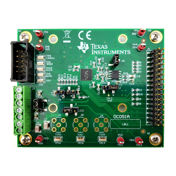
Page 13: Dac81416Evm Pcb Components Layout
PCB Components Layout Figure 13 through Figure 17 show the layout of the components for the DAC81416EVM board. Figure 13. DAC81416EVM PCB Components Layout SLAU777A – June 2018 – Revised December 2018 DAC81416EVM Submit Documentation Feedback Copyright © 2018, Texas Instruments Incorporated... -
Page 14: Top Layer
Schematic, PCB Layout, and Bill of Materials www.ti.com Figure 14. Top Layer DAC81416EVM SLAU777A – June 2018 – Revised December 2018 Submit Documentation Feedback Copyright © 2018, Texas Instruments Incorporated... -
Page 15: Layer 2 - Ground Plane
Schematic, PCB Layout, and Bill of Materials www.ti.com Figure 15. Layer 2 - Ground Plane SLAU777A – June 2018 – Revised December 2018 DAC81416EVM Submit Documentation Feedback Copyright © 2018, Texas Instruments Incorporated... -
Page 16: Layer 3 - Power Plane
Schematic, PCB Layout, and Bill of Materials www.ti.com Figure 16. Layer 3 - Power Plane DAC81416EVM SLAU777A – June 2018 – Revised December 2018 Submit Documentation Feedback Copyright © 2018, Texas Instruments Incorporated... -
Page 17: Bottom Layer
Schematic, PCB Layout, and Bill of Materials www.ti.com Figure 17. Bottom Layer SLAU777A – June 2018 – Revised December 2018 DAC81416EVM Submit Documentation Feedback Copyright © 2018, Texas Instruments Incorporated... -
Page 18: Dac81416 Evm Bill Of Materials
R1, R2, R12, R13, R14, 10.0k RES, 10.0 k, 1%, 0.1 W, 0603 RC0603FR-0710KL Yageo America R15, R16, R17 0603 DAC81416EVM SLAU777A – June 2018 – Revised December 2018 Submit Documentation Feedback Copyright © 2018, Texas Instruments Incorporated... - Page 19 Green (RoHS & no Sb/Br) Square Basket Heatsink Heat Sink TO-3 500403B00000G Aavid Featuring Slanted Fins J4, J5, J6 Connector, SMA, TH 142-0701-231 Cinch Connectivity SLAU777A – June 2018 – Revised December 2018 DAC81416EVM Submit Documentation Feedback Copyright © 2018, Texas Instruments Incorporated...
- Page 20 Changed connector.pin numbers in Table 5 to match the connector.pin numbers listed in Table 4 ................ • Changed connector numbers in Table 8; updated for clarity Revision History SLAU777A – June 2018 – Revised December 2018 Submit Documentation Feedback Copyright © 2018, Texas Instruments Incorporated...
- Page 21 STANDARD TERMS FOR EVALUATION MODULES Delivery: TI delivers TI evaluation boards, kits, or modules, including any accompanying demonstration software, components, and/or documentation which may be provided together or separately (collectively, an “EVM” or “EVMs”) to the User (“User”) in accordance with the terms set forth herein.
- Page 22 FCC Interference Statement for Class B EVM devices NOTE: This equipment has been tested and found to comply with the limits for a Class B digital device, pursuant to part 15 of the FCC Rules. These limits are designed to provide reasonable protection against harmful interference in a residential installation.
- Page 23 【無線電波を送信する製品の開発キットをお使いになる際の注意事項】 開発キットの中には技術基準適合証明を受けて いないものがあります。 技術適合証明を受けていないもののご使用に際しては、電波法遵守のため、以下のいずれかの 措置を取っていただく必要がありますのでご注意ください。 1. 電波法施行規則第6条第1項第1号に基づく平成18年3月28日総務省告示第173号で定められた電波暗室等の試験設備でご使用 いただく。 2. 実験局の免許を取得後ご使用いただく。 3. 技術基準適合証明を取得後ご使用いただく。 なお、本製品は、上記の「ご使用にあたっての注意」を譲渡先、移転先に通知しない限り、譲渡、移転できないものとします。 上記を遵守頂けない場合は、電波法の罰則が適用される可能性があることをご留意ください。 日本テキサス・イ ンスツルメンツ株式会社 東京都新宿区西新宿6丁目24番1号 西新宿三井ビル 3.3.3 Notice for EVMs for Power Line Communication: Please see http://www.tij.co.jp/lsds/ti_ja/general/eStore/notice_02.page 電力線搬送波通信についての開発キットをお使いになる際の注意事項については、次のところをご覧ください。http:/ /www.tij.co.jp/lsds/ti_ja/general/eStore/notice_02.page 3.4 European Union 3.4.1 For EVMs subject to EU Directive 2014/30/EU (Electromagnetic Compatibility Directive): This is a class A product intended for use in environments other than domestic environments that are connected to a low-voltage power-supply network that supplies buildings used for domestic purposes.
- Page 24 Notwithstanding the foregoing, any judgment may be enforced in any United States or foreign court, and TI may seek injunctive relief in any United States or foreign court. Mailing Address: Texas Instruments, Post Office Box 655303, Dallas, Texas 75265 Copyright © 2018, Texas Instruments Incorporated...
- Page 25 TI products. TI’s provision of these resources does not expand or otherwise alter TI’s applicable warranties or warranty disclaimers for TI products. Mailing Address: Texas Instruments, Post Office Box 655303, Dallas, Texas 75265 Copyright © 2018, Texas Instruments Incorporated...
Need help?
Do you have a question about the DAC81416EVM and is the answer not in the manual?
Questions and answers