Table of Contents
Advertisement
Quick Links
www.ti.com
EVM User's Guide: DAC80508-04EVM
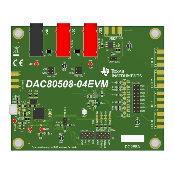
DAC80508-04 Evaluation Module
Description
The
DAC80508-04EVM
is an easy-to-use platform
to evaluate the functionality and performance of the
DACx0508
and
DACx0504
DAC80508-04EVM has optional circuits and jumpers
to configure the device for different applications. The
DAC80508 is installed on the EVM. The user can
replace the DAC80508 with the DAC80504.
The DAC80508 and DAC80504 are 16-bit buffered
voltage-output digital-to-analog converters (DAC).
The DAC80508 has 8 DACs, and the DAC80504
has 4 DACs. The devices includes a 2.5-V, 5-
ppm/°C internal reference and a user-selectable gain
configuration giving full-scale output voltages of 1.25
V, 2.5 V, or 5 V. The devices operate from a single
2.7-V to 5.5-V supply, is verified monotonic, and
provides exceptional linearity of ±1 LSB INL.
Get Started
1. Order the EVM.
2. Configure EVM jumpers.
SLAU920 – NOVEMBER 2023
Submit Document Feedback
family of devices. The
Copyright © 2023 Texas Instruments Incorporated
3. Install the DAC805xxEVM GUI from ti.com.
4. Connect USB and external power supplies.
5. Launch the DAC805xxEVM GUI.
Features
•
Configurable circuit to evaluate the DACx0508 and
DACx0504 family of devices
•
Onboard VDD (5-V or 3.3-V) and VIO (5-V, 3.3-V,
or 1.8-V) support via USB and on-board voltage
regulators
•
Option for external reference voltage or on-board
2.5-V reference voltage
•
Trigger output is available for synchronous
measurement
•
FT4232 easily writes to the DAC using the
DAC805xxEVM GUI
•
External SPI connections available
Applications
•
Optical networking
•
Wireless infrastructure
•
Industrial automation
•
Data acquisition systems
Description
DAC80508-04 Evaluation Module
1
Advertisement
Table of Contents

Subscribe to Our Youtube Channel
Related Manuals for Texas Instruments DAC80508-04EVM


Summary of Contents for Texas Instruments DAC80508-04EVM
- Page 1 Features DACx0508 DACx0504 family of devices. The DAC80508-04EVM has optional circuits and jumpers • Configurable circuit to evaluate the DACx0508 and to configure the device for different applications. The DACx0504 family of devices DAC80508 is installed on the EVM.
-
Page 2: Kit Contents
1.4 Device Information Table 1-2 lists the devices supported by the DAC80508-04EVM. DACx050x is used as a generic name for these devices. This document focuses on the DAC80508, which comes pre-installed on the EVM, and the DAC80504. Table 1-2. DAC80508-04EVM Supported Devices... - Page 3 FTDI controller onboard using SPI protocol. 2.1.1 Hardware Theory of Operation The DAC80508-04EVM is connected to the computer through the on-board FTDI digital controller using the USB cable that is supplied with the EVM. The evaluation board features connectors and test points for all communication lines, DAC outputs, and supplies.
-
Page 4: Jumper Definitions
Hardware www.ti.com 2.1.2 Jumper Definitions The jumpers must be connected properly to operate the DAC80508-04EVM. Table 2-1 provides the details of the configurable jumper settings of the DAC80508-04EVM. Figure 2-2 shows the default jumper connections on the board. Table 2-1. DAC80508-04EVM Jumper Definitions... -
Page 5: Connector Definitions
Hardware 2.1.3 Connector Definitions Table 2-2 shows the power connector definitions of the DAC80508-04EVM. Table 2-2. Power Connector Definitions Designator Definition SMA connector FTDI Trigger Input (unpopulated) USB connector DAC80508 VDD supply (2.7 V to 5.5 V) DAC80508 Ground DAC80508 VIO supply (1.7 V to 5.5 V) -
Page 6: Test Points
Hardware www.ti.com 2.1.4 Test Points The DAC80508-04EVM has a variety of test points available for measuring and debugging purposes. Table 2-5 explains the purpose of each test point. Table 2-5. DAC80508-04EVM Test Points Test Point Description 3p3V On-board 3.3-V supply 1p8V On-board 1.8-V supply... -
Page 7: Hardware Overview
2.2.1 Electrostatic Discharge Caution CAUTION Many of the components on the DAC80508-04EVM are susceptible to damage by electrostatic discharge (ESD). Customers are advised to observe proper ESD handling precautions when unpacking and handling the EVM, including the use of a grounded wrist strap at an approved ESD workstation. -
Page 8: Software Installation
When the DAC805xx GUI is launched, an installation dialog window opens and prompts the user to select an installation directory. If left unchanged, Figure 3-1 shows that the software location defaults to C:\Program Files (x86)\Texas Instruments\DAC805xxEVM. Figure 3-1. Software Installation Path DAC80508-04 Evaluation Module SLAU920 – NOVEMBER 2023 Submit Document Feedback Copyright © 2023 Texas Instruments Incorporated... - Page 9 Figure 3-2 shows the FTDI USB drivers installation window that is automatically launched after the DAC805xxEVM software installation is complete. Figure 3-2. FTDI USB Drivers SLAU920 – NOVEMBER 2023 DAC80508-04 Evaluation Module Submit Document Feedback Copyright © 2023 Texas Instruments Incorporated...
-
Page 10: Software Overview
GUI after launch with the DAC80504 register map loaded. Figure 3-5 shows the GUI after launch with the DAC80508 register map loaded. Figure 3-4. DAC805xxEVM GUI DAC80504 Selection at Launch DAC80508-04 Evaluation Module SLAU920 – NOVEMBER 2023 Submit Document Feedback Copyright © 2023 Texas Instruments Incorporated... - Page 11 DEMO MODE or CONNECTED. After the FTDI controller is properly connected to the computer, restart the DAC805xxEVM software to detect the device. Figure 3-6. FTDI Digital Controller Connection Status SLAU920 – NOVEMBER 2023 DAC80508-04 Evaluation Module Submit Document Feedback Copyright © 2023 Texas Instruments Incorporated...
- Page 12 Data are written to the registers by entering a value in the value column of the GUI. Figure 3-7. DAC80504 Low Level Configuration Page DAC80508-04 Evaluation Module SLAU920 – NOVEMBER 2023 Submit Document Feedback Copyright © 2023 Texas Instruments Incorporated...
- Page 13 Software Figure 3-8. DAC80508 Low Level Configuration Page SLAU920 – NOVEMBER 2023 DAC80508-04 Evaluation Module Submit Document Feedback Copyright © 2023 Texas Instruments Incorporated...
- Page 14 DAC80508 tab from the High Level Configuration page. This tab is used to set the gain and output for the DACs. The internal reference and the reference division can also be powered on and off here. DAC80508-04 Evaluation Module SLAU920 – NOVEMBER 2023 Submit Document Feedback Copyright © 2023 Texas Instruments Incorporated...
- Page 15 Software Figure 3-10. DAC80508 Tab of the High Level Configuration Page SLAU920 – NOVEMBER 2023 DAC80508-04 Evaluation Module Submit Document Feedback Copyright © 2023 Texas Instruments Incorporated...
- Page 16 Hardware Design Files www.ti.com 4 Hardware Design Files 4.1 Schematics The DAC80508-04EVM schematics are shown in Figure 4-1 through Figure 4-2. 1p8V 5V_USB 10uF 3p3V VIO SEL VDD SEL 10uF TP10 100nF 100nF TP13 10nF 10nF 10nF 10nF 10nF 10nF...
- Page 17 Figure 4-6 show the board layout for the DAC80508-04EVM. Figure 4-3. DAC80508-04EVM PCB Top Layer Layout Figure 4-4. DAC80508-04EVM PCB Mid Layer 1 Layout (Ground Plane) SLAU920 – NOVEMBER 2023 DAC80508-04 Evaluation Module Submit Document Feedback Copyright © 2023 Texas Instruments Incorporated...
- Page 18 Hardware Design Files www.ti.com Figure 4-5. DAC80508-04EVM PCB Mid Layer 2 Layout (Power Plane) Figure 4-6. DAC80508-04EVM PCB Bottom Layer Layout DAC80508-04 Evaluation Module SLAU920 – NOVEMBER 2023 Submit Document Feedback Copyright © 2023 Texas Instruments Incorporated...
-
Page 19: Bill Of Materials
Hardware Design Files 4.3 Bill of Materials Table 4-1 lists the DAC80508-04EVM BOM. Table 4-1. Bill of Materials for the DAC80508-04EVM Package Designator Value Description Part Number Manufacturer Reference CAP, CERM, 4.7 µF, 16 V,+/- C1, C2, C5 4.7 µF... - Page 20 Hardware Design Files www.ti.com Table 4-1. Bill of Materials for the DAC80508-04EVM (continued) Package Designator Value Description Part Number Manufacturer Reference Thermal Transfer Printable PCB Label 0.650 x LBL1 Labels, 0.650" W x 0.200" H THT-14-423-10 Brady 0.200 inch - 10,000 per roll 10 kΩ...
- Page 21 Hardware Design Files Table 4-1. Bill of Materials for the DAC80508-04EVM (continued) Package Designator Value Description Part Number Manufacturer Reference Automotive 4-Bit Fixed Direction Voltage-Level Texas Translator with Schmitt- UQFN12 TXU0304RUT Instruments Trigger Inputs, and Tri-State Outputs Future Technology Devices...
-
Page 22: Related Documentation
Texas Instruments integrated circuits used in the assembly of the DAC80508-04EVM. This user's guide is available from the TI web site under literature number SLAU920. Any letter appended to the literature number corresponds to the document revision that is current at the time of the writing of this document. - Page 23 STANDARD TERMS FOR EVALUATION MODULES Delivery: TI delivers TI evaluation boards, kits, or modules, including any accompanying demonstration software, components, and/or documentation which may be provided together or separately (collectively, an “EVM” or “EVMs”) to the User (“User”) in accordance with the terms set forth herein.
- Page 24 www.ti.com Regulatory Notices: 3.1 United States 3.1.1 Notice applicable to EVMs not FCC-Approved: FCC NOTICE: This kit is designed to allow product developers to evaluate electronic components, circuitry, or software associated with the kit to determine whether to incorporate such items in a finished product and software developers to write software applications for use with the end product.
- Page 25 www.ti.com Concernant les EVMs avec antennes détachables Conformément à la réglementation d'Industrie Canada, le présent émetteur radio peut fonctionner avec une antenne d'un type et d'un gain maximal (ou inférieur) approuvé pour l'émetteur par Industrie Canada. Dans le but de réduire les risques de brouillage radioélectrique à...
- Page 26 www.ti.com EVM Use Restrictions and Warnings: 4.1 EVMS ARE NOT FOR USE IN FUNCTIONAL SAFETY AND/OR SAFETY CRITICAL EVALUATIONS, INCLUDING BUT NOT LIMITED TO EVALUATIONS OF LIFE SUPPORT APPLICATIONS. 4.2 User must read and apply the user guide and other available documentation provided by TI regarding the EVM prior to handling or using the EVM, including without limitation any warning or restriction notices.
- Page 27 Notwithstanding the foregoing, any judgment may be enforced in any United States or foreign court, and TI may seek injunctive relief in any United States or foreign court. Mailing Address: Texas Instruments, Post Office Box 655303, Dallas, Texas 75265 Copyright © 2023, Texas Instruments Incorporated...
-
Page 28: Important Notice
TI products. TI’s provision of these resources does not expand or otherwise alter TI’s applicable warranties or warranty disclaimers for TI products. TI objects to and rejects any additional or different terms you may have proposed. IMPORTANT NOTICE Mailing Address: Texas Instruments, Post Office Box 655303, Dallas, Texas 75265 Copyright © 2023, Texas Instruments Incorporated...
Need help?
Do you have a question about the DAC80508-04EVM and is the answer not in the manual?
Questions and answers