
Related Manuals for Baicells Nova430e


Summary of Contents for Baicells Nova430e
- Page 1 Nova430e Outdoor 4x250mW Two-Carrier TDD eNodeB Installation Guide QRTB 2.9.4 March 2022 Version 1.01...
- Page 2 Documents. Copyright Notice Baicells Technologies, Inc., copyrights the information in this document. No part of this document may be reproduced in any form or means without the prior written consent of Baicells Technologies, Inc. Disclaimer The information in this document is subject to change at any time without notice. For more information, please consult with a Baicells technical engineer or the support team.
- Page 3 Resources Documentation - Baicells product data sheets, this document, and other technical • manuals can be found at Baicells.com > Resources > Documents. • Support - How to open a support ticket, process an RMA, and the Support Forum are at Baicells.com >...
-
Page 4: Table Of Contents
Table of Contents 1 Overview ..........................7 1.1 Introduction ........................7 1.2 Features.......................... 8 2 Installation Preparation ......................10 2.1 Materials ........................10 2.2 LEDs and Interfaces ....................... 12 2.3 Location and Environment .................... 13 2.4 Grounding and Lightning Protection ................13 2.5 Weatherproofing ...................... - Page 5 Appendix: Regulatory Compliance ..................... 40 FCC Compliance ........................40 ISEDC Compliance ....................... 40 List of Figures Figure 1-1: Nova430e eNB ......................7 Figure 1-2: Network Structure ...................... 7 Figure 2-1: Packout ........................10 Figure 2-2: LEDs and Interfaces ....................12 Figure 2-3: Weatherproofing ......................
- Page 6 Figure 3-18: WAN/LAN/VLAN ..................... 29 Figure 3-19: LGW ........................30 Figure 3-20: LGW = Router......................32 Figure 3-21: Static Routing......................32 Figure 3-22: Management Server ....................33 Figure 3-23: Quick Setting ......................35 Figure 3-24: Carrier Setting ......................36 Figure 3-25: Reboot ........................37 Figure 3-26: Cell Status (eNB GUI)....................
-
Page 7: Overview
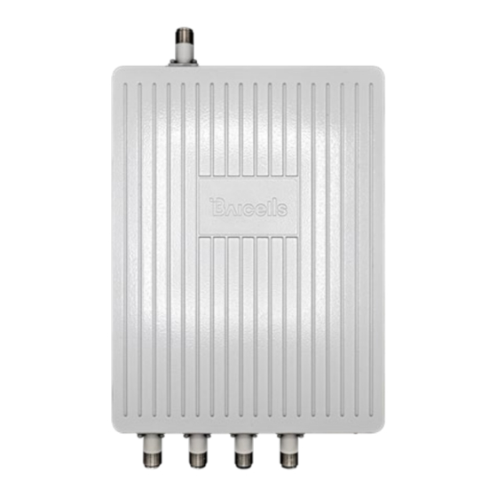
Overview 1.1 Introduction The Baicells Nova430e (Figure 1-1) is an advanced two-carrier outdoor eNodeB (eNB) that is compliant with Third-Generation Partnership Project (3GPP) on Long-Term Evolution (LTE) Time Division Duplex (TDD) technology. This 4x250mW eNodeB can operate in Carrier Aggregation (CA) mode or Dual Carrier (DC)/split mode. -
Page 8: Features
Features. The Nova430e primary cell (Pcell) is referred to as Cell 1. The secondary cell (Scell) is referred to as Cell 2. Each eNB is pre-configured to simplify the installation. Baicells provides operators with local and Web-based Graphical User Interface (GUI) software applications to configure and manage individual eNBs and Customer Premise Equipment (CPE). - Page 9 HaloB User Guide • SAS Deployment Guide In addition to the Nova430e eNB two carriers and multiple operating modes, the following is a list of other key features. The Nova430e datasheet providing technical specifications is kept up-to-date on the Baicells website.
-
Page 10: Installation Preparation
Installation Preparation 2.1 Materials Check the Nova430e package to ensure it contains the primary components in the packout (Figure 2-1). In addition to industry-standard tools, you will need the materials described in Table 2-1 and the tools shown in Table 2-2 during the installation. -
Page 11: Table 2-1: Materials
Table 2-1: Materials Item Description Power cable < 16 AWG, e.g., 14 AWG, shorter than 330 feet (100 meters) Power plug The plug that connects the power cable to the electricity supply RF antenna cable 50 ohm feeder, ½ jumper RF antenna Omni or directional dual polarized antenna Ethernet cable... -
Page 12: Leds And Interfaces
2.2 LEDs and Interfaces Figure 2-2, Table 2-3, and Table 2-4 explain the eNB status indicators and interfaces. Figure 2-2: LEDs and Interfaces Table 2-3: LEDs Color Status Description Steady on Power is on Green No power supply CELL1 is inactive CELL1 Green Fast flash: 0.1 s on, 0.1 s off... -
Page 13: Location And Environment
External antenna interface 4, N type connector 2.3 Location and Environment The Nova430e can be installed on a pole or a wall. For the best signal coverage, place the eNB in an unobstructed location. In addition to network planning, when determining where to place the eNB, you need to consider the best location for signal coverage. -
Page 14: Weatherproofing
2.5 Weatherproofing For Radio Frequency (RF) antenna weatherproofing, use cold shrink tubes. To protect the connection points from weather and climate, clean each connection point before installing cold shrink tubes, per the following (Figure 2-3). Insert the cable into the cold shrink tube. Tighten the connector. -
Page 15: Cloudcore Account
2.6 CloudCore Account The Baicells CloudCore includes the Evolved Packet Core (EPC), managed by Baicells, and two operator applications, Operations Management Console (OMC) to manage network elements, and Business and Operation Support System (BOSS) to manage subscribers. If you have not already set up a Baicells CloudCore account, follow the steps below. -
Page 16: Install Gps Antenna
3.2 Install GPS Antenna WARNING: Ensure the antenna is connected before powering up the eNB. The wireless signal transmission power can cause bodily injury and damage to the eNB and RF power amplifier devices. Read the following GPS antenna installation requirements before installing it on the eNB and refer to Figure 3-2. -
Page 17: Install Enb On Pole Or Wall
Figure 3-3: GPS Antenna Installation After assembling the GPS antenna, the connector must be waterproofed with all-weather electrical tape and mastic tape. Refer to section 2.5. 3.3 Install eNB on Pole or Wall 3.3.1 Install on Pole The eNB mounting bracket is assembled in manufacturing before packing. The only action required by the installer is to attach the assembly to the pole. -
Page 18: Figure 3-5: Attach Bracket To Pole
Figure 3-5: Attach Bracket to Pole 3. Using the two pins on the bracket on the back of the eNB, attach the eNB to the mounting bracket on the pole. Push the eNB until the hook is firmly attached to the mounting bracket (Figure 3-6). -
Page 19: Install On Wall
3.3.2 Install on Wall Ensure that the wall can bear at least four times the weight of the eNB. Follow the steps below to install the Nova430e eNB on a wall. 1. Take apart the assembled installation bracket. 2. Place the assembled bracket on the wall with the arrow facing upward, as shown in Figure 3-8. -
Page 20: Connect Cables
5. Using the two pins on the back of the unit bracket, attach the eNB to the bracket on the wall. Push the eNB until the hook is firmly attached to the mounting bracket. Tighten the bolt on the top of the bracket using a cross screwdriver to complete the installation (Figure 3-10). -
Page 21: Connect Rf Cables
3.4.2 Connect RF Cables WARNING: Ensure the antenna is connected before powering up the eNB. The wireless signal transmission power can cause bodily injury and damage to the eNB and RF power amplifier devices. 1. Open the dust caps of the ANT0, ANT1, ANT2, and ANT3 interfaces. 2. -
Page 22: Figure 3-11: Pole Grounding
Figure 3-11: Pole Grounding The installation position of the grounding bar should meet the design requirements. The holding pole and tower body must be connected to the lightning protection network or grounded with a separate lead. The diameter of the grounding wire should meet the design requirements. The copper nose must be used for grounding, and the grounding resistance is required to be less than 10 ohms. -
Page 23: Connect Grounding Cable
Prepare the grounding cable according to the actual measurements and requirements of the specific installation site. The Nova430e eNB has two grounding screws located on the bottom of the unit, as shown in Figure 3-12. Follow the steps below the figure to connect the ground cable. -
Page 24: Maintenance Chamber Waterproofing
RF power amplifier devices. After the Nova430e is powered on, check that the LED indicators are lighting as expected: Power is steady green, cell activated is slow flash green, and there are no alarms (Figure 3-14) per... -
Page 25: Configure Basic Parameters
Reference: eNodeB Configuration Guide The Nova430e eNB can be configured in Single Carrier (SC), Carrier Aggregation (CA), or Dual Carrier (DC)/split mode, depending on which licenses you have purchased, and/or in HaloB mode, which is embedded in the base software. The Nova430e also supports CBRS SAS operation. -
Page 26: Figure 3-15: Gui Login
Figure 3-16: Home Page Optionally, you may want to: 1. Change the login password. 2. Confirm the firmware version is the latest available from Baicells website; upgrade if needed. Firmware upgrades can be found at Baicells.com > Support > Firmware. See Section 3.7.2 for detailed instructions regarding firmware upgrades. -
Page 27: Upgrade Firmware
To ensure you are using the most recent software version before configuring the eNB, follow the steps below. 3.7.2.1 Upgrade Firmware from eNB GUI 1. Download the most recent firmware file from Baicells.com > Support > Firmware, and save on local computer. -
Page 28: Basic Configuration Overview
3.7.3 Basic Configuration Overview Figure 3-17 indicates four main steps for basic configuration: network interfaces, management server address, quick settings pertaining to key LTE parameters, and the carrier setting. Figure 3-17: Configuration Flow 3.7.4 Configure Network Interfaces The network interfaces defined as part of the initial, basic setup include the WAN/LAN/VLAN interfaces, Dynamic Host Configuration Protocol (DHCP), and the Local Gateway (LGW) mode. -
Page 29: Figure 3-18: Wan/Lan/Vlan
NOTE: If the LAN IP address is changed, the eNB will reboot, and you will have to log in to the GUI again. Figure 3-18: WAN/LAN/VLAN... -
Page 30: Figure 3-19: Lgw
VLAN when there is a need to transmit multi-types of data. 3.7.4.2 LGW The Local GateWay (LGW) setting must be configured when using the Baicells CloudCore Evolved Packet Core (EPC). Refer to Figure 3-19 and Table 3-2. You must reboot the eNB when you make changes to these settings. -
Page 31: Table 3-2: Lgw
Table 3-2: LGW Field Name Description On or Off LGW Mode Select an option: NAT: Packages from the internal network to the external network need Network Address Translation Router: Select optimized route from the routing table (Figure 3-20) Bridge: Transfer in the data link layer LGW Interface Binding The IP address connects to the LGW. -
Page 32: Figure 3-20: Lgw = Router
Figure 3-20: LGW = Router 3.7.4.3 Static Routing When using static routing, go to Network > Static Routing. The landing page has two main sections, Static Routing Config and Validated Route List (Figure 3-21). The configured static route information will be displayed under Static Routing Config. To edit a static route in the list, click on the edit icon, enter the information, and click OK. -
Page 33: Configure The Management Server
In the BTS Setting > Management Server window, you will enter the network management service (NMS) information (Figure 3-22). When using the Baicells CloudCore to manage the network, in the http:// field, enter the following URL address and port number: baiomc.cloudapp.net:48080/smallcell/AcsService... -
Page 34: Configure Quick Settings
Frequency will auto-fill based on the eNB hardware model. Make sure the Cloud EPC field is set to ON when using the Baicells CloudCore. If you are testing the eNB in a lab environment, turn the power down as low as it will go under the Power Modify field. -
Page 35: Figure 3-23: Quick Setting
NOTE 1: If planning to use CBRS SAS, the SAS vendor will determine some of these parameters. Refer to the SAS Deployment Guide for more information. NOTE Nova430e does not support SFA = 0. For a description of all the eNB Quick Setting fields, refer to the eNodeB Configuration Guide. -
Page 36: Configure Carrier Setting
Carrier Aggregation & Dual Carrier (Split Mode) Configuration Guide The Carrier Setting menu is used only in the two-carrier Nova430e eNB (Figure 3-24). You can set the eNB to run as a single carrier, as two combined carriers using Carrier Aggregation (CA), or as two independent carriers using Dual Carrier (DC)/split mode, depending on which licenses you have purchased. -
Page 37: Verify Enb Operational Status
Figure 3-25: Reboot 3.7.9 Verify eNB Operational Status When the eNB is finished rebooting, check the eNB status using the eNB GUI and the OMC. Once the eNB is mounted at its intended destination and powered on, recheck the status settings. eNB GUI: Go to Basic Setting >... -
Page 38: Figure 3-26: Cell Status (Enb Gui)
Figure 3-26: Cell Status (eNB GUI) Figure 3-27: Cell Status (OMC) -
Page 39: Figure 3-28: Omc > Enb > Monitor > Display Settings
Figure 3-28: OMC > eNB > Monitor > Display Settings Before commercial operation, Baicells recommends implementing cell site acceptance testing of a new site to ensure the service meets expectations, to document network speeds at various locations in the cell, and to verify RF coverage. -
Page 40: Appendix: Regulatory Compliance
Appendix: Regulatory Compliance FCC Compliance This device complies with part 15 of the FCC Rules. Operation is subject to the following two conditions: (1) This device may not cause harmful interference, and (2) this device must accept any interference received, including interference that may cause undesired operation. Any Changes or modifications not expressly approved by the party responsible for compliance could void the user's authority to operate the equipment.
Need help?
Do you have a question about the Nova430e and is the answer not in the manual?
Questions and answers