Table of Contents
Advertisement
Quick Links
Advertisement
Table of Contents

Related Manuals for Sensaphone WEB600


Summary of Contents for Sensaphone WEB600
- Page 1 USER’S MANUAL VERSION 2.4 SENSAPHONE ® REMOTE MONITORING SOLUTIONS...
- Page 2 Every effort has been made to ensure that the information in this document is complete, accurate and up-to-date. Sensaphone assumes no responsibility for the results of errors beyond its control. Sensaphone also cannot guarantee that changes in equipment made by other manufacturers, and referred to in this manual, will not affect the applicability of the information in this manual.
- Page 3 • Read and follow all warning and instruction labels on the product itself. • To protect the Web600 from overheating, make sure all openings on the unit are not blocked. Do not place on or near a heat source, such as a radiator or heat register.
- Page 4 WEB600 User’s Manual Part 15: This equipment has been tested and found to comply with the limits for a Class A digital device, pursuant to Part 15 of the FCC Rules. These limits are designed to provide reasonable protection against harmful interference when the equipment is operated in a commercial environment.
- Page 5 THIS LIMITED WARRANTY CONTAINS SENSAPHONE’S STANDARD TERMS AND CONDITIONS. WHERE PERMITTED BY THE APPLICABLE LAW, BY KEEPING YOUR SENSAPHONE PRODUCT BEYOND THIRTY (30) DAYS AFTER THE DATE OF DELIVERY, YOU FULLY ACCEPT THE TERMS AND CONDITIONS SET FORTH IN THIS LIMITED WARRANTY.
- Page 6 WEB600 User’s Manual IT MUST BE CLEAR THAT THE WARRANTORS ARE NOT INSURING YOUR PREMISES OR BUSINESS OR GUARANTEEING THAT THERE WILL NOT BE DAMAGE TO YOUR PERSON OR PROPERTY OR BUSINESS IF YOU USE THIS PRODUCT. YOU SHOULD MAINTAIN INSURANCE COVERAGE SUFFICIENT TO PROVIDE COMPENSATION FOR ANY LOSS, DAMAGE, OR EXPENSE THAT MAY ARISE IN CONNECTION WITH THE USE OF PRODUCTS OR SERVICES, EVEN IF CAUSED BY WARRANTORS’...
-
Page 7: Table Of Contents
RESETTING THE WEB600 TO FACTORY DEFAULT SETTINGS . . . . . . . . . . . . . . . . . - Page 8 WEB600 User’s Manual CHAPTER 4: USER PROGRAMMING ....27 CONTACT PROGRAMMING . . . . . . . . . . . . . . . . . . . . . . . . . . . . . . . . . . . . . . . . . . . . . . . . . . . . . . . . . . . . . . . .28 E-MAIL PROGRAMMING .
-
Page 9: Chapter 1: Installation
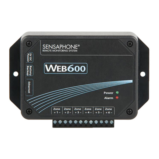
CHAPTER 1: INSTALLATION INTRODUCTION Congratulations on your purchase of the Sensaphone Web600 Monitoring System. The system is designed to be an easy, cost–effective, network–based monitoring system to notify you when equipment or conditions go awry. The internet browser–based programming makes the device easy to use from any computer on your network. -
Page 10: Installation And Configuration
6) Status LEDs RJ-45 10/100BASE-T ETHERNET PORT This jack is for connecting to your network so that the Web600 can send alarm messages and display it’s webpage. Two LEDs indicate when the Web600 has a valid link (green) and transmitted/received data (yellow). -
Page 11: Installation
115VAC 60 Hz outlet within 6’ WALL MOUNT INSTALLATION The Web600 can be wall mounted using the included dry wall anchors and screws. Follow the steps below: 1) Install two drywall anchors (if necessary) 5” apart. Attach the Web600 using the two #6 tapping screws. -
Page 12: Connecting Sensors
WEB600 User’s Manual CONNECTING SENSORS The Web600 is compatible with a wide variety of sensors including normally open/normally closed con- tacts, 2.8K and 10K temperature sensors, and 4–20mA current sources. Contact Sensaphone or your Sensaphone reseller for assistance in selecting sensors for your monitoring requirements. A list of sen- sors and accessories is shown in Appendix C. -
Page 13: Normally Open / Normally Closed Dry Contacts
Wiring a Dry Contact Sensor 2.8K/10K TEMPERATURE SENSORS The Web600 is compatible with 2.8K/10K temperature sensors that match the curve data listed in the tables in Appendix F. The monitoring temperature range of the 2.8K thermistor is -109 to 115ºF (-85º... -
Page 14: 4-20Ma Current Loop Transducers
RELAY OUTPUT WIRING The WEB600 includes an SPST relay output that can be used to turn on a light, siren, or other device whenever an alarm occurs. The output is a normally open dry contact that can be used for low voltage switching. -
Page 15: Battery Backup (Optional)
The percent charge can be viewed on the Summary screen. Note that upon initial connection it may take up to 5 minutes for the unit to discover that a battery has been connected. Once the WEB600 sees the battery it will enable the battery channel on the Battery programming screen (see Zones menu). To receive a low battery alarm you must enable Alarm Message Delivery and configure the Alarm Schedule accordingly. - Page 16 Network Administrator. 2) Using a network hub connect only your PC and the Web600 to the hub. Change the IP of your net- work connection to something in 192.168.1.xxx that is not the same as the default IP of the Web600.
-
Page 17: Network Parameter Descriptions
Web600 Ethernet port. There is a unique address for all network devices. IP/Host: This is the entry field for manually configuring the IP address of the Web600 on your network. This address is provided by you or your network administrator. It is formatted as a standard dotted deci- mal number. -
Page 18: Installing The Sensaphone Locator Software
The Sensaphone Locator software is used to find your WEB600 on your network. This is convenient when your WEB600 was configured using DHCP since it will tell you the IP address that was assigned to your WEB600 and provide a Connect button to open a web browser window to the device’s web page. Installation Instructions 1. -
Page 19: Using The Sensaphone Locator Software
RESETTING THE WEB600 TO FACTORY DEFAULT SETTINGS In the event that you can no longer connect to your WEB600 or simply have forgotten the password, you can reset the unit to factory defaults. On the bottom of the enclosure is a small hole. Beneath the hole is a push button. -
Page 20: Chapter 2: System Configuration
This screen also provides an entry for a Time Server. This can be used to periodically synchronize the system clock to keep it accurate. Simply enter the address of a time server in this field and the WEB600 will automatically synchronize to it on a periodic basis. You can enter a host name or IP address in this field. -
Page 21: Network
Chapter 2: System Configuration sages to all profiles at priority level 1. Then it will wait the duration of the Escalation Delay and send messages to priority level 2, as long as the alarm still exists, and so on with priority 3, 4, 5,…. If the alarm no longer exists, those profiles who have higher escalation levels will not be contacted. -
Page 22: Smtp
587 is also becoming more common as well. Note that the Web600 will not work with SMTP servers that require TLS or SSL encryption. As a result, it will not work with web-based e-mail providers such Gmail, Hotmail, Yahoo!Mail, or AOL. If you do not have a compatible SMTP server available to you then contact Sensaphone Technical support for other options. -
Page 23: Modbus
The complete WEB600 OID information is available in Appendix E. MODBUS® The WEB600 can be accessed via Modbus®TCP protocol and function as a slave device. To use this fea- ture select the desired Modbus® Mode, Port number, and Bit Representation for your Modbus® network. -
Page 24: Chapter 3: Zone Programming
This chapter explains how to program the Zone Inputs for monitoring and alarming based on your requirements. The WEB600 features numerous settings for customizing the operation of the device. To begin, click on Zones from the menu bar. The following screen will appear: Zones page The Zone Programming page displays each of the six Zones, as well as Battery and Power monitoring. - Page 25 Alarm Reset Time: This is the time allowed for an alarm’s fault condition to be corrected before the WEB600 resets (reactivates) the alarm and begins the message delivery process all over again. It is rec- ommended that this be set to no lower than 30 minutes to prevent numerous messages from being sent.
- Page 26 • If you only log 1 zone (at any interval), the Web600 will store a maximum of 115, 800 samples • If you log 6 zones at the same interval, the Web600 will store 39,900 samples of each zone •...
- Page 27 User Programming Screen The WEB600 allows you to have up to 8 User Profiles. Each Profile can have up to 4 contact meth- ods; e-mail, SMS-Text Message, or SNMP trap. You can choose to have a secure system with separate Usernames and Passwords for each user, or you can choose to make the device accessible with no secu- rity (e.g.
- Page 28 Schedule Programming Screen CONTACT PROGRAMMING The WEB600 allows you to program up to 4 Contacts per User. The Contacts can be either: E-mail, SMS-Text Message, or SNMP Trap. Each contact can have a programmable Schedule so that you only receive messages when your Contact schedule is enabled. A Test button is also provided to check your programming.
- Page 29 Chapter 4: User Programming SMS-TEXT MESSAGE PROGRAMMING To configure a SMS-Text Message choose SMS-Text Message from the drop-down list and enter your telephone number in the field below. Choose your wireless provider from the drop-down list. Configure the Contact Schedule if desired. SNMP TRAP To configure an SNMP Trap choose SNMP Trap from the drop-down list and enter your SNMP Server Name or IP address in the field below.
- Page 30 WEB600 User’s Manual CHAPTER 5: HISTORY This chapter explains how to query the Event and Data Log History. The Event Log is a time-stamped list of system events such as System Startup, Alarm Detection, Message Delivery, … The Data Log con- tains time stamped records of the input values.
Need help?
Do you have a question about the WEB600 and is the answer not in the manual?
Questions and answers