Table of Contents
Advertisement
Quick Links
Advertisement
Table of Contents

Related Manuals for Sensaphone WEB600


Summary of Contents for Sensaphone WEB600
- Page 1 USER’S MANUAL VERSION 1.2.8...
- Page 2 Every effort has been made to ensure that the information in this document is complete, accurate and up-to-date. Sensaphone assumes no responsibility for the results of errors beyond its control. Sensaphone also cannot guarantee that changes in equipment made by other manufacturers, and referred to in this manual, will not affect the applicability of the information in this manual.
-
Page 3: Important Safety Instructions
Important Safety Instructions Your Web600 has been carefully designed to give you years of safe, reliable performance. As with all electrical equipment, however, there are a few basic precautions you should take to avoid hurting your- self or damaging the unit: reference. - Page 4 WEB600 User’s Manual FCC Requirements Part 15: This equipment has been tested and found to comply with the limits for a Class A digital device, pursuant to Part 15 of the FCC Rules. These limits are designed to provide reasonable protection against harmful interference when the equipment is operated in a commercial environment.
- Page 5 1 YEAR LIMITED WARRANTY WARRANTOR ELEMENTS OF WARRANTY WARRANTY AND REMEDY PURCHASER.
- Page 6 WEB600 User’s Manual PROCEDURE FOR OBTAINING PERFORMANCE OF WARRANTY LEGAL REMEDIES AND DISCLAIMER CHOICE OF FORUM AND CHOICE OF LAW 901 Tryens Road Aston, PA 19014 Phone: 610.558.2700 Fax: 610.558.0222 www.sensaphone.com...
-
Page 7: Table Of Contents
RESETTING THE WEB600 TO FACTORY DEFAULT SETTINGS ........ - Page 8 WEB600 User’s Manual CHAPTER 3: ZONE PROGRAMMING ....23 CHAPTER 4: USER PROGRAMMING ....27 CONTACT PROGRAMMING .
-
Page 9: Chapter 1: Installation
CHAPTER 1: INSTALLATION INTRODUCTION Congratulations on your purchase of the Sensaphone Web600 Monitoring System. The system is designed to be an easy, cost–effective, network–based monitoring system to notify you when equipment or conditions go awry. The internet browser–based programming makes the device easy to use from any computer on your network. -
Page 10: Installation And Configuration
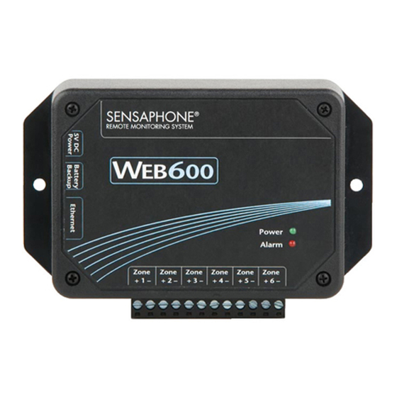
5) Status LEDs RJ-45 10/100BASE-T ETHERNET PORT This jack is for connecting to your network so that the Web600 can send alarm messages and display it’s webpage. Two LEDs indicate when the Web600 has a valid link (green) and transmitted/received data (yellow). -
Page 11: Installation
32º –122º Fahrenheit (0º– 50º C) WALL MOUNT INSTALLATION The Web600 can be wall mounted using the included dry wall anchors and screws. Follow the steps below: 1) Install two drywall anchors (if necessary) 5” apart. Attach the Web600 using the two #6 tapping screws. -
Page 12: Connecting Sensors
WEB600 User’s Manual CONNECTING SENSORS The Web600 is compatible with a wide variety of sensors including normally open/normally closed con- tacts, 2.8K and 10K temperature sensors, and 4–20mA current sources. Contact Sensaphone or your Sensaphone reseller for assistance in selecting sensors for your monitoring requirements. A list of sen- sors and accessories is shown in Appendix C. -
Page 13: Normally Open / Normally Closed Dry Contacts
Wiring a Dry Contact Sensor 2.8K/10K TEMPERATURE SENSORS The Web600 is compatible with 2.8K/10K temperature sensors that match the curve data listed in the to 57ºC) and the 10K thermistor is -87° to 168°F (-66° to 76°C). Temperature sensors can be connected directly to the zone terminals without regard for polarity. -
Page 14: 4-20Ma Current Loop Transducers
The percent charge can be viewed on the Summary screen. Note that upon initial connection it may take up to 5 minutes for the unit to discover that a battery has been connected. Once the WEB600 sees the battery it will enable the battery channel on the Battery programming screen (see Zones menu). To... -
Page 15: Network Configuration
The Web600 is designed for installation on an Ethernet network. This involves assigning it an IP cessful you can then use the Sensaphone Locator program to find the Web600 on your network and then assign it a fixed IP address. The network configurations page can be found on the Network tab within... -
Page 16: Network Parameter Descriptions
Network Administrator. 2) Using a network hub connect only your PC and the Web600 to the hub. Change the IP of your net- After navigating to the network configuration page, you should now be able to access the network con- figurations of your Web600 and set them accordingly. -
Page 17: Installing The Sensaphone Locator Software
INSTALLING THE SENSAPHONE LOCATOR SOFTWARE The Sensaphone Locator software is used to find your WEB600 on your network. This is convenient to your WEB600 and provide a Connect button to open a web browser window to the device’s web page. Installation Instructions 1. -
Page 18: Resetting The Web600 To Factory Default Settings
RESETTING THE WEB600 TO FACTORY DEFAULT SETTINGS In the event that you can no longer connect to your WEB600 or simply have forgotten the password, you can reset the unit to factory defaults. On the bottom of the enclosure is a small hole. Beneath the hole is a push button. -
Page 19: Chapter 2: System Configuration
This screen also provides an entry for a Time Server. This can be used to periodically synchronize the system clock to keep it accurate. Simply enter the address of a time server in this field and the WEB600 will automatically synchronize to it on a periodic basis. You can enter a host name or IP address in this field. -
Page 20: Network
WEB600 User’s Manual messages to all users at priority level 1. Then it will wait the duration of the Escalation Delay and send messages to priority level 2, as long as the alarm still exists, and so on with priority 3, 4, 5,…. If the alarm no longer exists, those users who have higher escalation levels will not be contacted. -
Page 21: Smtp
587 is also becoming more common as well. Note that the Web600 will not work with SMTP servers that require TLS or SSL encryption. As a result, not have a compatible SMTP server available to you then contact Sensaphone Technical support for other options. -
Page 22: Modbus
The complete WEB600 OID information is available in Appendix E. MODBUS® The WEB600 can be accessed via Modbus®TCP protocol and function as a slave device. To use this fea- ture select the desired Modbus® Mode, Port number, and Bit Representation for your Modbus® network. -
Page 23: Chapter 3: Zone Programming
This chapter explains how to program the Zone Inputs for monitoring and alarming based on your requirements. The WEB600 features numerous settings for customizing the operation of the device. To begin, click on Zones from the menu bar. The following screen will appear:... - Page 24 Alarm Reset Time: This is the time allowed for an alarm’s fault condition to be corrected before the WEB600 resets (reactivates) the alarm and begins the message delivery process all over again. It is rec- ommended that this be set to no lower than 30 minutes to prevent numerous messages from being sent.
- Page 25 Chapter 3: Zone Programming Datalogging Mode: The WEB600 has two modes of data logging for each zone: Continuous or While In Alarm. In Continuous mode the unit will log the value of the input on a fixed time interval all the time.
- Page 26 WEB600 User’s Manual...
-
Page 27: Chapter 4: User Programming
User Programming Screen The WEB600 allows you to have up to 8 Users. Each User can have up to 4 contact (e-mail, SMS- Text Message, or SNMP trap). You can choose to have a secure system with separate Usernames and Passwords for each user, or you can choose to make the device accessible with no security (e.g. -
Page 28: Contact Programming
Pic of Schedule CONTACT PROGRAMMING The WEB600 allows you to program up to 4 Contacts per User. The Contacts can be either: E-mail, SMS-Text Message, or SNMP Trap. Each contact can have a programmable Schedule so that you only receive messages when your Contact schedule is enabled. A Test button is also provided to check your programming. -
Page 29: Sms-Text Message Programming
Chapter 4: User Programming SMS-TEXT MESSAGE PROGRAMMING To configure a SMS-Text Message choose SMS-Text Message from the drop-down list and enter your telephone number in the field below. Choose your wireless provider from the drop-down list. Configure the Contact Schedule if desired. SNMP TRAP To configure an SNMP Trap choose SNMP Trap from the drop-down list and enter your SNMP Server Name or IP address in the field below. - Page 30 WEB600 User’s Manual...
-
Page 31: Chapter 5: History
Chapter 5: History CHAPTER 5: HISTORY list of system events such as System Startup, Alarm Detection, Message Delivery, … The Data Log con- tains time stamped records of the input values. The logging rate is configured on the Zone programming screen for each input. - Page 32 WEB600 User’s Manual your query, the choices are 25, 50, 100 and All. Finally, click the View Data button to display the results. Alternatively you can Export the results to a file for viewing in another program. Choose the Export file format from the drop-down list (XML, CSV, TXT) and click the Export button to create a file.
-
Page 33: Chapter 6: Operation
User. The Web600 will now check to see if any Contacts are enabled. Any Contacts that are not Enabled will immediately be discarded from receiving the alarm message. Next, the unit will check the Contact Alarm Delivery Schedule. -
Page 34: Return-To-Normal Alarm Messages
In the event that the Ethernet network (or e-mail server) becomes unavailable due to a service disrup- tion or power failure, the WEB600 will hold the current alarm messages until service is restored, how- ever, if both power and battery fail or the alarm no longer exists before the network services are restored... -
Page 35: Appendix A: Weekly Testing Procedure
AC adapter after the unit has finished. 4.) Keep a log of your tests, noting the date and whether the Web600 passed in each category tested. An example of such a log is shown below. (See “Test Log” at the end of this manual.) - Page 36 WEB600 User’s Manual...
-
Page 37: Appendix B: Accessories
Appendix B: Accessories APPENDIX B: ACCESSORIES The sensors listed below are available from Sensaphone, and represent the most commonly used zone devices. Other dry contact sensors, designed for more specialized applications, may also be used. Commercial or industrial electrical supply houses can provide devices to monitor virtually any condi- tion. - Page 38 WEB600 User’s Manual...
-
Page 39: Appendix C: Modbus® Specifications
Appendix C: Modbus® specifications APPENDIX C: MODBUS® SPECIFICATIONS Inputs TYPE VALID RANGE BASE OFFSET Input Calibration (fixed-point integer) sint16 ±300.00 4x10496 Normal Logging Frequency (max 31 days) uint32 0 - 2678400 s. 4x10500 Alarm Logging Frequency (max 31 days) uint32 0 - 2678400 s. - Page 40 WEB600 User’s Manual Password for login string 0 - 16 characters 4x00812 Profile Schedule 42-byte array Any Value 4x00828 Enable/Disable Profile TRUE or FALSE 0x00512 CONTACTS TYPE VALID RANGE BASE OFFSET e-mail address string 0 - 64 characters 4x02144 Type of communication (voice, e-mail, SMS)
-
Page 41: Modbus® Notes
3x00000 - 3x65535 word, read-write 4x00000 - 4x65535 The memory types map to the Modbus® commands as shown in the following table. The Web600 supports Modbus® conformance classes 0 and 1. Address Type Modbus® Commands 1, 5, 15 3, 6, 16 Address Calculation Modbus®... - Page 42 WEB600 User’s Manual Quick Access Table The following is a quick access table to retrieve the word-access, read-only current input values as human-readable ASCII strings. Use the Modbus® command “4” to access the data. Address Description 3x01552 Zone 1 3x01594 Zone 2...
- Page 43 Appendix C: Modbus® specifications NON-GENERIC DATA Timestamps Timestamps can be decoded using the following equations. “div” means integer division where the remainder is dropped. “mod” means the “modulus” or “remainder”. All values start at “0”. For example, Day 0 is the first day of the month and Month 0 is January.
- Page 44 WEB600 User’s Manual Contact Types: Contact Type Description Email or SMS SNMP Trap Modbus® Configuration: Operating Mode Description Modbus® Disabled Read-Only Read-Write Bit Representation Description Big-Endian Byte Order Little-Endian Word Order (Modbus® Default) Big-Endian Byte Order Big-Endian Word Order (Network Byte Order)
-
Page 45: Appendix D: Specifications
Appendix D: Specifications APPENDIX D: SPECIFICATIONS ALERT ZONES Number of Zones: 6 Zone Connector: terminal block (-87° to 168°F; -66° to 76°C), and 4-20mA (-80,000.0 to 80,000.0 Zone Characteristics: 28.7KΩ to 3.3V (temperature/contact) or 250 Ohms to ground (4-20mA) A/D Converter Resolution: 12 bits ±2 LSB Zone Protection: 5.5VDC Metal Oxide Varistor with fast acting diode clamps. -
Page 46: Environmental
WEB600 User’s Manual ENVIRONMENTAL Operating Temperature: 32–122° F (0–50° C) Storage Temperature: 32°–140° F (0–60° C) PHYSICAL Weight: 1.5 lbs. (680 grams) Enclosure: Indoor-rated plastic housing suitable for wall or desktop installation. -
Page 47: Appendix E: Oid Information
Appendix E: OID Information APPENDIX E: OID INFORMATION WEB 600 OID INFO ZONE INFORMATION ZONE NAMES .1.3.6.1.4.1.8338.1.1.4.1.1.1.1.15 ZONE 1 Name .1.3.6.1.4.1.8338.1.1.4.1.1.1.2.15 ZONE 2 Name .1.3.6.1.4.1.8338.1.1.4.1.1.1.3.15 ZONE 3 Name .1.3.6.1.4.1.8338.1.1.4.1.1.1.4.15 ZONE 4 Name .1.3.6.1.4.1.8338.1.1.4.1.1.1.5.15 ZONE 5 Name .1.3.6.1.4.1.8338.1.1.4.1.1.1.6.15 ZONE 6 Name .1.3.6.1.4.1.8338.1.1.4.1.1.1.8.15 Internal Power Name ZONE LABEL UNITS ZONE CALIBRATION... - Page 48 WEB600 User’s Manual ZONE RECOGNITION TIME (IN SECONDS) .1.3.6.1.4.1.8338.1.1.4.1.1.1.1.16 ZONE 1 RECOGNITION TIME .1.3.6.1.4.1.8338.1.1.4.1.1.1.2.16 ZONE 2 RECOGNITION TIME .1.3.6.1.4.1.8338.1.1.4.1.1.1.3.16 ZONE 3 RECOGNITION TIME .1.3.6.1.4.1.8338.1.1.4.1.1.1.4.16 ZONE 4 RECOGNITION TIME .1.3.6.1.4.1.8338.1.1.4.1.1.1.5.16 ZONE 5 RECOGNITION TIME .1.3.6.1.4.1.8338.1.1.4.1.1.1.6.16 ZONE 6 RECOGNITION TIME .1.3.6.1.4.1.8338.1.1.4.1.1.1.8.16 Internal Power RECOGNITION TIME ZONE RESET TIME (IN SECONDS) .1.3.6.1.4.1.8338.1.1.4.1.1.1.1.17 ZONE 1 RESET TIME...
- Page 49 Appendix E: OID Information .1.3.6.1.4.1.8338.1.1.4.1.1.1.6.14 ZONE 6 LOW LIMIT .1.3.6.1.4.1.8338.1.1.4.1.1.1.8.14 Internal Power LOW LIMIT REAL TIME ZONE VALUES .1.3.6.1.4.1.8338.1.1.4.1.1.1.1.48 ZONE 1 REAL TIME VALUE .1.3.6.1.4.1.8338.1.1.4.1.1.1.2.48 ZONE 2 REAL TIME VALUE .1.3.6.1.4.1.8338.1.1.4.1.1.1.3.48 ZONE 3 REAL TIME VALUE .1.3.6.1.4.1.8338.1.1.4.1.1.1.4.48 ZONE 4 REAL TIME VALUE .1.3.6.1.4.1.8338.1.1.4.1.1.1.5.48 ZONE 5 REAL TIME VALUE .1.3.6.1.4.1.8338.1.1.4.1.1.1.6.48 ZONE 6 REAL TIME VALUE .1.3.6.1.4.1.8338.1.1.4.1.1.1.8.48 Internal Power REAL TIME VALUE...
- Page 50 WEB600 User’s Manual .1.3.6.1.4.1.8338.1.1.4.1.1.1.6.40 ZONE 6 MINIMUM VALUE .1.3.6.1.4.1.8338.1.1.4.1.1.1.8.40 Internal Power MINIMUM VALUE ZONE MAXIMUM VALUES .1.3.6.1.4.1.8338.1.1.4.1.1.1.1.41 ZONE 1 MAXIMUM VALUE .1.3.6.1.4.1.8338.1.1.4.1.1.1.2.41 ZONE 2 MAXIMUM VALUE .1.3.6.1.4.1.8338.1.1.4.1.1.1.3.41 ZONE 3 MAXIMUM VALUE .1.3.6.1.4.1.8338.1.1.4.1.1.1.4.41 ZONE 4 MAXIMUM VALUE .1.3.6.1.4.1.8338.1.1.4.1.1.1.5.41 ZONE 5 MAXIMUM VALUE .1.3.6.1.4.1.8338.1.1.4.1.1.1.6.41 ZONE 6 MAXIMUM VALUE...
- Page 51 Appendix E: OID Information .1.3.6.1.4.1.8338.1.1.4.1.1.1.6.25 ZONE 6 RESET TIME ENABLED/DISABLED .1.3.6.1.4.1.8338.1.1.4.1.1.1.8.25 Internal Power RESET TIME ENABLED/DISABLED ZONE TABLE LOW .1.3.6.1.4.1.8338.1.1.4.1.1.1.1.13 ZONE 1 TABLE LOW .1.3.6.1.4.1.8338.1.1.4.1.1.1.2.13 ZONE 2 TABLE LOW .1.3.6.1.4.1.8338.1.1.4.1.1.1.3.13 ZONE 3 TABLE LOW .1.3.6.1.4.1.8338.1.1.4.1.1.1.4.13 ZONE 4 TABLE LOW .1.3.6.1.4.1.8338.1.1.4.1.1.1.5.13 ZONE 5 TABLE LOW .1.3.6.1.4.1.8338.1.1.4.1.1.1.6.13 ZONE 6 TABLE LOW .1.3.6.1.4.1.8338.1.1.4.1.1.1.8.13 Internal Power TABLE LOW ZONE TABLE HIGH...
-
Page 52: Datalogger
WEB600 User’s Manual CURRENT ZONE TYPE DATALOGGER ZONE DATALOG NORMAL INTERVAL (IN SECONDS) .1.3.6.1.4.1.8338.1.1.4.1.1.1.1.4 ZONE 1 NORMAL INTERVAL .1.3.6.1.4.1.8338.1.1.4.1.1.1.2.4 ZONE 2 NORMAL INTERVAL .1.3.6.1.4.1.8338.1.1.4.1.1.1.3.4 ZONE 3 NORMAL INTERVAL .1.3.6.1.4.1.8338.1.1.4.1.1.1.4.4 ZONE 4 NORMAL INTERVAL .1.3.6.1.4.1.8338.1.1.4.1.1.1.5.4 ZONE 5 NORMAL INTERVAL .1.3.6.1.4.1.8338.1.1.4.1.1.1.6.4 ZONE 6 NORMAL INTERVAL .1.3.6.1.4.1.8338.1.1.4.1.1.1.8.4 Internal Power NORMAL INTERVAL... -
Page 53: Gauge Settings
Appendix E: OID Information GAUGE SETTINGS GAUGE LOW SETTING .1.3.6.1.4.1.8338.1.1.4.1.1.1.1.33 ZONE 1 GAUGE LOW .1.3.6.1.4.1.8338.1.1.4.1.1.1.2.33 ZONE 2 GAUGE LOW .1.3.6.1.4.1.8338.1.1.4.1.1.1.3.33 ZONE 3 GAUGE LOW .1.3.6.1.4.1.8338.1.1.4.1.1.1.4.33 ZONE 4 GAUGE LOW .1.3.6.1.4.1.8338.1.1.4.1.1.1.5.33 ZONE 5 GAUGE LOW .1.3.6.1.4.1.8338.1.1.4.1.1.1.6.33 ZONE 6 GAUGE LOW .1.3.6.1.4.1.8338.1.1.4.1.1.1.8.33 Internal Power GAUGE LOW GAUGE HIGH SETTING PROFILE INFORMATION PROFILE ENABLED... - Page 54 WEB600 User’s Manual .1.3.6.1.4.1.8338.1.1.4.1.4.1.7.6 PROFILE 7 NAME .1.3.6.1.4.1.8338.1.1.4.1.4.1.8.6 PROFILE 8 NAME Profile Escalation Level...
-
Page 55: Appendix F: Thermistors
Appendix F: Thermistors APPENDIX F: THERMISTORS 2.8K THERMISTOR DATA Degrees Celsius Resistance (Ohms) 187,625 27,180 5,572 2,256 10K THERMISTOR DATA Degrees Celsius Resistance (Ohms) 441.3K 135.2K 47.54K 12.25K 2,760 1,458 1,084 816.8 481.8 376.4 237.0... - Page 56 WEB600 User’s Manual...
-
Page 57: Appendix G: Returning The Unit For Repair
APPENDIX G: RETURNING THE UNIT FOR REPAIR In the event that the WEB600 does not function properly, we suggest that you do the following: 1) Record your observations regarding the WEB600’s malfunction. 2) Call the Technical Service Department at 610-558-2700 prior to sending the unit to Sensaphone for repair. - Page 58 WEB600 User’s Manual...
-
Page 59: Appendix H: Test Log
Appendix H: Test Log APPENDIX H: TEST LOG Alarms... - Page 60 WEB600 User’s Manual Alarms...
Need help?
Do you have a question about the WEB600 and is the answer not in the manual?
Questions and answers