Table of Contents
Advertisement
Quick Links
Advertisement
Table of Contents

Related Manuals for Sensaphone IMS-4000


Summary of Contents for Sensaphone IMS-4000
- Page 1 USER’S MANUAL VERSION 4.1...
- Page 2 Every effort has been made to ensure that the information in this document is complete, accurate and up-to-date. Sensaphone assumes no responsibility for the results of errors beyond its control. Sensaphone also cannot guarantee that changes in equipment made by other manufacturers, and referred to in this manual, will not affect the applicability of the information in this manual.
-
Page 3: Important Safety Instructions
• To reduce the risk of electric shock, do not disassemble this product, but return it to Sensaphone Customer Service, or another approved repair facility, when any service or repair work is required. Opening or removing covers may expose you to dangerous voltages or other risks. -
Page 4: Wichtige Sicherheitshinweise
• Um das Stromschlagrisiko zu senken, das Produkt nicht zerlegen, sondern bei erforderlichen Wartungs- oder Reparaturarbeiten zum Sensaphone-Kundendienst oder zu einer anderen zugelassenen Werkstatt geben. Beim Öffnen oder Entfernen von Abdeckungen und Blenden bestehen verschiedene Gefahren, wie etwa die Möglichkeit des Kontakts mit gefährlichen Spannungen. -
Page 5: Fcc Requirements
FCC REQUIREMENTS Part 68: The Sensaphone IMS-4000E complies with 47 CFR, Part 68 of the rules. On the back of the unit there is a label that contains, among other information, the Certification Number and the Ringer Equivalence Number (REN) for this equipment. -
Page 6: Telephone Consumer Protection Act (Host Only)
IMS-4000 Manual TELEPHONE CONSUMER PROTECTION ACT (HOST ONLY) The FCC Telephone Consumer Protection Act of 1991 makes it unlawful for any person to use a computer or other electronic device, including FAX machines, to send a message unless such message contains, in a margin at the top or... - Page 7 Portions relating to PNG copyright 1999, 2000, 2001, 2002 Greg Roelofs. Portions relating to gdttf.c copyright 1999, 2000, 2001, 2002 John Ellson (ellson@lucent.com). Portions relating to gdft.c copyright 2001, 2002 John Ellson (ellson@lucent.com). Portions relating to JPEG and to color quantization copyright 2000, 2001, 2002, Doug Becker and copyright © 1994, 1995, 1996, 1997, 1998, 1999, 2000, 2001, 2002, Thomas G.
-
Page 8: Year Limited Warranty
PLEASE READ THIS WARRANTY CAREFULLY BEFORE USING THE PRODUCT. THIS LIMITED WARRANTY CONTAINS SENSAPHONE’S STANDARD TERMS AND CONDI- TIONS. WHERE PERMITTED BY THE APPLICABLE LAW, BY KEEPING YOUR SENSAPHONE PRODUCT BEYOND THIRTY (30) DAYS AFTER THE DATE OF DELIVERY, YOU FULLY ACCEPT THE TERMS AND CONDITIONS SET FORTH IN THIS LIMITED WARRANTY. - Page 9 LOSS OF BUSINESS, LOSS OF DATA OR INFORMATION, OR FINANCIAL LOSS, FOR CLAIMS OF ANY NATURE, INCLUDING BUT NOT LIMITED TO CLAIMS IN CONTRACT, BREACH OF WAR- RANTY OR TORT, AND WHETHER OR NOT CAUSED BY WARRANTORS’ NEGLIGENCE. WITHOUT WAIVING ANY PROVISION IN THIS LIMITED WARRANTY, IF A CIRCUMSTANCE ARISES WHERE WARRANTORS ARE FOUND TO BE LIABLE FOR ANY LOSS OR DAMAGE ARIS- ING OUT OF MISTAKES, NEGLIGENCE, OMISSIONS, INTERRUPTIONS, DELAYS, ERRORS OR DEFECTS IN WARRANTORS’...
- Page 10 IMS-4000 Manual applicable, the Uniform Commercial Code as adopted by the State of Delaware shall apply. 4. PROCEDURE FOR OBTAINING PERFORMANCE OF WARRANTY: In the event that the Product does not conform to this warranty, the Product should be shipped or delivered freight prepaid to a War- rantor with evidence of original purchase.
-
Page 11: Table Of Contents
User’s Manual Version 4 0 Important Safety Instructions ................3 Wichtige Sicherheitshinweise . - Page 12 IMS-4000 Manual Network Setup using the webpage: . . . . . . . . . . . . . . . . . . . . . . . . . . . . . . . . . . . . . . . . . . . . . . . . . . . . . . . . . . . . . . . . . . . .23 Network Setup using the serial port: .
- Page 13 Connect Environmental Sensors to Host and Node(s) . . . . . . . . . . . . . . . . . . . . . . . . . . . . . . . . . . . . . . . . . . . . . . . . . .37 Configure User Profiles and Contacts .
- Page 14 IMS-4000 Manual Configuring User Profiles . . . . . . . . . . . . . . . . . . . . . . . . . . . . . . . . . . . . . . . . . . . . . . . . . . . . . . . . . . . . . . . . . . . . . . . . . . . . . . . 5 6 Adding a Profile .
- Page 15 Exporting Data . . . . . . . . . . . . . . . . . . . . . . . . . . . . . . . . . . . . . . . . . . . . . . . . . . . . . . . . . . . . . . . . . . . . . . . . . . . . . . . . . . . . . . . . .75 Copying to the Clipboard .
- Page 16 Software . . . . . . . . . . . . . . . . . . . . . . . . . . . . . . . . . . . . . . . . . . . . . . . . . . . . . . . . . . . . . . . . . . . . . . . . . . . . . . . . . . . . . . . . . . . . . .130 Appendix C: IMS-4000E Accessories Appendix D: License Agreement for Sensaphone® IMS-4000E ConsoleView Software Appendix E: Returning an IMS Unit for Repair Test Log .
-
Page 17: Chapter 1: Installation
• Integrated webpage for device configuration and management. • SNMP v1 & v3 supported. TECHNICAL SUPPORT If any questions arise upon installation or operation of the IMS-4000E, please contact the Sensaphone Technical Service Department at 610.558.2700 and have the following information available: • Date of purchase __________________ •... -
Page 18: Host Installation And Configuration
IMS-4000 Manual tures. You should thoroughly read this manual to establish a basic understanding of the system and keep it as a refer- ence. HOST INSTALLATION AND CONFIGURATION PHYSICAL DESCRIPTION The IMS-4000E Host is housed in a 17”w x 1.75”h x 10”d enclosure, which is 1 EIA rack-mount space high. -
Page 19: Sensor Inputs
Chapter 1: Installation CAUTION: Never install telephone wiring during a lightning storm. Never install telephone jacks in wet locations unless the jack is specifically designed for wet locations. Never touch uninsulated telephone wires or terminals unless the telephone line has been disconnected at the network interface. Use caution when installing or modifying telephone lines. -
Page 20: Ac Power And Battery Leds
IMS-4000 Manual Mode 6: Sensor in trouble Green: QUICK FLASH Red: QUICK FLASH AC POWER AND BATTERY LEDS The AC Power and Battery alarm status is indicated by two red LEDs. Their modes of operation are described below. Mode 1:... -
Page 21: Operating Environment
Chapter 1: Installation OPERATING ENVIRONMENT Before you install the IMS-4000E Host be sure that your operating environment meets the physical requirements of the equipment. Operating Temperature: 32º–122º Fahrenheit (0º–50º C) Humidity: 5–90 %RH, non-condensing Power: 100–250VAC 50–60 Hz outlet within 6’ Rack Requirements: Standard 19”... -
Page 22: Tabletop Installation
IMS-4000 Manual Figure 4: Wall-mounted Host Unit TABLETOP INSTALLATION The IMS-4000E Host can be installed on a tabletop or shelf. Follow the steps below: 1) Attach the four self-adhesive rubber feet to the four corners on the bottom of the IMS-4000E. -
Page 23: Network Configuration
(using either method) to configure the device’s network settings: Network Setup using the webpage: 1) Download and install the Sensaphone Locator software utility from the Sensaphone.com website (IMS- 4000E>Support). 2) Connect the IMS-4000E to a 10/100 switch on your network, turn the unit on, and run the Locator Software on a computer on the same network. - Page 24 IMS-4000 Manual If you select Option 1 you will see the IP address and status of the Host and all associated nodes. A sample is shown below: Enterprise Status Unit Type IP Status IMS-4000E Monitor Host 10.1.4.10 Ok NY_Node Node 10.1.4.17 Ok Press any key to return to main menu Option 2 will display the network configuration for the Host as well as web server, RAS, and two-way email settings.
-
Page 25: Local Configuration Definitions
Chapter 1: Installation Option 9 (Enable default Master Administrator Account (temporarily) should only be used in the event that no Master Administrator accounts can be accessed (e.g. the password(s) were forgotten). Enabling this feature will temporari- ly load the default Master Administrator account (username: admin, password: ims4k). This temporary account will unload if any one of the following occurs: (1) Any of the Master Administrator accounts are edited, (2) A new Master Administrator account is created, or... -
Page 26: Battery Maintenance
Voice mode. Disabling this feature will prevent the microphone from being accessed during a telephone call. Sensaphone Locator: Software application for Windows that will display the IP address for all Sensaphone IMS4000 Host and Node devices on the local network (if enabled on the device). -
Page 27: Replacing The Battery
Chapter 1: Installation Replacing the Battery The battery in the Host can be replaced by following the instructions listed below. Be sure to read all safety messages and follow the instructions in order as listed. Several tools will be required to change the battery: •... - Page 28 IMS-4000 Manual Step 13) Re-install in rack. Step 14) Re-attach the power cord. Step 15) Re-connect the phone line. Step 16) Turn the Power Switch back on. Akkumulator austauschen Der Austausch des Akkumulators im Host verläuft gemäß den nachfolgenden Schritten. Lesen Sie alle Sicherheitshinweise aufmerksam durch und folgen Sie den Anweisungen in der angegebenen Reihenfolge.
-
Page 29: Ims Host Specifications
Chapter 1: Installation IMS HOST SPECIFICATIONS OPERATING SPECIFICATIONS Temperature: 32-122°F Humidity: 5–90% RH non-condensing Power Supply: 100–250VAC 50–60Hz Power Consumption (Typ): 25 Watts Dimensions: 1.75”h x 9.5”d x 19”w Backup Battery: 12V 2.9AH Sealed Gel Cell Backup Time: 3.5 Hours COMMUNICATION SPECIFICATIONS Ethernet: 10/100 Base-T, 10/100Mbps RS-232: DB9, 9600bps, DTE... -
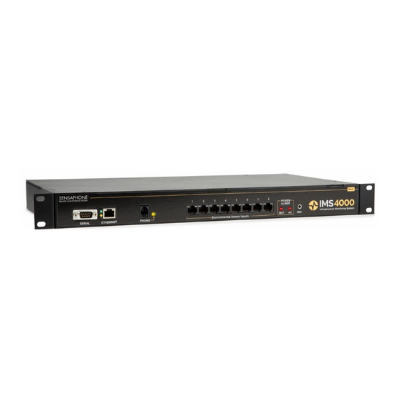
Page 30: Sensor Inputs
IMS-4000 Manual 1 Sensor Inputs 2 Microphone Jack 3 Internal Microphone 4 Ethernet Port (10/100BASE-T) 5 Serial Port 6 Power Switch 7 Power LED SENSOR INPUTS The sensor inputs are designed to interface with IMS-4000E series sensors (See Chapter 6). The use of RJ-45 jacks for sensor inputs allows the use of existing structured cabling to connect remote sensors. -
Page 31: Parts Required
Chapter 1: Installation • Connecting sensors • Replacing the battery Parts Required Phillips Screwdriver • 9 pin F/F null modem cable • Dumb terminal or PC w/9 pin com port OPERATING ENVIRONMENT Before you install the IMS-4000E Node be sure that your operating environment meets the physical requirements of the equipment. -
Page 32: Rack Mount Installation
IMS-4000 Manual Austausch des Akkumulators Der IMS-4000E-Knoten verwendet als Reservestromquelle für Stromausfälle einen (1) wiederaufladbaren Akkumulator (6 V, 3,4 Ah; im Lieferumfang enthalten). Das Gerät lädt diesen Akkumulator auf, sobald es an das Netz angeschlossen und der Netzschalter eingeschaltet ist. -
Page 33: Wall Mount Installation
Chapter 1: Installation WALL MOUNT INSTALLATION The IMS-4000E Node can be wall mounted using the optional wall mount brackets. Follow the steps below: 1) Attach the optional wall mount brackets to the sides of the IMS-4000E using the eight black #6-32 screws. A Phillips screwdriver will be required. -
Page 34: Network Configuration
• 9600 baud, no parity, 8 data bits, 1 stop bit, no flow control To get online with the IMS-4000E Node, connect your terminal to the serial port and press <RETURN>. A menu will appear which will guide you through the setup. Sensaphone IMS Node Unit Version: 3.10 Main Menu 1. -
Page 35: Local Configuration Definitions
Chapter 1: Installation Option 5 will allow you to perform some diagnostic tests to see if the Node can connect to its Host. Option 6 will reboot the system. You must reboot for new Network settings to take effect. Option 7 will logout without rebooting. LOCAL CONFIGURATION DEFINITIONS Parent Host IP Address: This is the IP address of the IMS-4000E Host that this Node is associated with. -
Page 36: Chapter 2: Ims-4000E Software
The ConsoleView Software can be downloaded from the Sensaphone.com website by navigating to Support, then Technical Support, then Sensaphone IMS-4000. Select the Downloads tab and find the link for “IMS-4000 ConsoleView Download. -
Page 37: Default Username And Password
Chapter 2: IMS-4000E Software DEFAULT USERNAME AND PASSWORD For new units, the default username is admin and the default password is ims4k. The software will now attempt to con- nect to your IMS-4000E Host. A progress bar will show the software retrieving information from the Host. Note: Do not save the default username and password, because it will be deleted automatically once a Master System Administrator profile is configured. -
Page 38: Configure User Profiles And Contacts
IMS-4000 Manual CONFIGURE USER PROFILES AND CONTACTS Program the User Profiles and Contacts to control who has access to the IMS-4000E and who gets contacted when an alarm occurs. Each user must have a Username, Password, and User Code. Right-click on Profiles and select Add New Profile. -
Page 39: Software Installation And Hardware Requirements
Microsoft Windows® version 7, 8, or 10 SOFTWARE INSTALLATION The IMS-4000E ConsoleView Software can be downloaded from the Sensaphone.com website. Go to the IMS-4000E Host product page, then select the ‘Downloads’ tab. The IMS-4000E ConsoleView Software setup program makes instal- lation quick and easy. -
Page 40: Starting The Ims-4000E Consoleview Software
IMS-4000 Manual STARTING THE IMS-4000E CONSOLEVIEW SOFTWARE Double-click the IMS-4000E icon to start the IMS-4000E ConsoleView Software. The software will automatically try to connect to all IMS-4000E Hosts that have been configured. If this is the first time you are running the software, you will need to create an Enterprise Group and add a Host within each Enterprise. -
Page 41: Connecting To A Host
Chapter 2: IMS-4000E Software Note: Do not save the default username and password, because it will be deleted automatically once a Master System Administrator profile is configured. Figure 7: Entering the Host address To see the programming, inputs, and accessories associated with the host, click in the box beside your enterprise group. The tree hierarchy will appear beneath the Host. - Page 42 IMS-4000 Manual Next, select the Phone Settings tab. Enter the telephone number of the Host in the Numeric Unit ID field. The Numeric Unit ID will appear on alarm messages delivered to numeric pagers and fax machines. Figure 10: Phone Settings tab Select a custom voice message to identify your Host by clicking the arrow in the Custom Voice field and selecting a voice file.
-
Page 43: Adding A Node
Chapter 2: IMS-4000E Software The IMS-4000E can be programmed to synchronize its clock to a reference time server every night at midnight. To use this feature the IMS-4000E must have network access to a server which supports one of the following time code proto- cols: Network Time Protocol - NTP (RFC-1035) Time Protocol - TP (RFC-868) -
Page 44: Changing Host Network Settings Using Consoleview
IMS-4000 Manual CHANGING HOST NETWORK SETTINGS USING CONSOLEVIEW You can remotely change the Host network settings using the ConsoleView software if the Allow Remote Configuration option is set in the Local Configuration options. However, before doing so consider the following: If you have any Nodes associated with the Host, they will stop communicating with Host if you change the IP address. -
Page 45: Sample Application
Chapter 2: IMS-4000E Software Note that if an alarm is detected, the Node will transmit this information to the Host immediately. The Node Properties screen is shown below: Figure 14: Node Properties Setup Tab Sample Application: 1) Suppose you are concerned about network traffic generated by Node-to-Host communication but want to view input values that are no more than 20 minutes old. -
Page 46: Configuring Environmental Inputs
IMS-4000 Manual CONFIGURING ENVIRONMENTAL INPUTS Each host or node can have up to 8 external sensors connected. The host or node will automatically identify what sen- sor type is connected to each input. Note that some newer sensors will require a subtype to be manually programmed. -
Page 47: Editing The Schedule
Chapter 2: IMS-4000E Software Schedule: Click this button to bring up the Edit Schedule screen. This screen allows you to set times when the channel is enabled or disabled. The blue line indicates days/times when the channel is enabled. Figure 18: Sensor Schedule screen The schedule example above enables the sensor Mon-Fri 8AM to 5PM. -
Page 48: Alarm Response Via The Powergate, Powergate2, Or Camera
IMS-4000 Manual Custom Voice: Click the drop down arrow and select the custom voice message you would like assigned to this sensor/ channel. Voice messages can be recorded on your PC and uploaded into the IMS-4000E on the Custom Voice Manager screen (See Recording and Uploading Voice Messages). -
Page 49: Camera Snapshots On Alarm
Chapter 2: IMS-4000E Software CAMERA SNAPSHOTS ON ALARM Camera images may be sent to one or more users when an Environmental or IP alarm occurs. Up to four alarm responses (PowerGate or Camera Snapshot) may be programmed per input. To configure this feature choose Alarm Response from the Properties screen for the chosen input. -
Page 50: Realtime Strip Chart
IMS-4000 Manual REALTIME STRIP CHART A realtime Strip Chart will show continuous values for sensors which provide an analog value. Just click on the sensor name and the chart will appear. The high and low scale of the chart is based on the Min and Max values. To reset Min/Max values, click on the Reset button to the right of the chart. -
Page 51: Removing/Changing A Sensor
Chapter 2: IMS-4000E Software REMOVING/CHANGING A SENSOR Since the Host and Node monitor the presence of sensors, you must be careful when removing them to prevent a trou- ble alarm from occurring. The following procedure is recommended: a) Disable the sensor you wish to change/remove by clearing its schedule. b) Disconnect the sensor from the Host or Node. -
Page 52: Configuring Ip Alarms
IMS-4000 Manual CONFIGURING IP ALARMS IP ALARM SETUP Each host or node can monitor up to 64 IP addresses through pinging and port availability. In addition, IP dependen- cies can be programmed to prevent multiple alarm messages from being sent when common network paths are down. -
Page 53: Editing The Schedule
Chapter 2: IMS-4000E Software Figure 27: IP Schedule screen The schedule example above enables the IP alarm 24 hours a day, including holidays. Editing the schedule: • Click on the All button in the top left corner of the grid to enable/disable the entire week. •... -
Page 54: Alarm Logic
IMS-4000 Manual Reset Time: This is the time allowed for an acknowledged alarm’s fault condition to be corrected before the IMS-4000E resets (reactivates) the alarm and begins the message delivery process all over again. The minimum reset time is 30 minutes. -
Page 55: Removing An Ip Alarm
Chapter 2: IMS-4000E Software Note: DO NOT set the Alarm Reset Time too short, otherwise you will continue to dispatch the same alarm over and over resulting in numerous phone calls, e-mails, etc. Figure 28: IP Alarm Flowchart REMOVING AN IP ALARM Expand the IP Alarms and right-click on the IP Alarm you wish to remove. -
Page 56: Configuring User Profiles And Contacts
IMS-4000 Manual Classes, expand the Settings menu, then right-click on Classes and select Properties. Several classes have been pre-de- fined in the IMS-4000E to give you a starting point. The default Classes are: • (Diagnostic) • Temperature • Humidity • Water •... -
Page 57: Adding A Profile
Chapter 2: IMS-4000E Software ADDING A PROFILE Right click on Profiles and select Add New Profile. The following screen will appear: Figure 30: User Profile screen The Name, Company, Department, and Title information are used to identify the user on reports that the unit sends. The Username, Password, and User Code are used for security purposes. -
Page 58: Permissions
IMS-4000 Manual PERMISSIONS Each user profile has a programmable security level for each device (host/nodes) in the system. To set the Security Access level click the Permissions button. There are three access levels: Master System Administrator, Site Administrator, and User. The restrictions for each security level is as follows …... -
Page 59: Classes
Chapter 2: IMS-4000E Software To configure profiles for Site Administrator or User security levels, select the appropriate Host or Node(s) and click the arrow to copy the Host/Node(s) into the appropriate list. The double arrow >> will copy all units to the list while the single arrow >... -
Page 60: Adding Contacts
IMS-4000 Manual that you can have certain Contacts be Enabled during daytime hours and others Enabled during nighttime hours. Only Contacts which are Enabled when the alarm occurs, will be contacted. The order of Contacts can be changed at any time. To move a Contact up or down in the list, click and hold the Contact you wish to move and drag it to its new location, then release the mouse button. -
Page 61: Numeric Pager Calls
Chapter 2: IMS-4000E Software These codes can be useful if you want to call an extension within a business. For example, suppose your office was answered by an auto-attendant, but you know that if you dialed the extension the call would be transferred. In this case you can program the telephone number, insert a w to wait for the auto-attendant to answer, and then add the extension you want dialed. -
Page 62: Schedule
IMS-4000 Manual SCHEDULE Click the Schedule button to bring up the Schedule screen for this Contact. Choose the times you want the Contact to be enabled by adjusting the blue bars. Areas where the blue bar appears indicates the day and time the Contact is Enabled. -
Page 63: Reconnecting
Chapter 2: IMS-4000E Software RECONNECTING At times your PC and IMS-4000E Host units may become disconnected. This may happen due to a system restart or other communication-related problem. You can reconnect to an IMS-4000E using the Reconnect command. To recon- nect to a unit, click on File from the main menu and select Reconnect. - Page 64 IMS-4000 Manual Click on the New button. This will display the MS Windows Sound Recorder program shown below. Figure 37: Sound Recorder screen For the voice messages to play back correctly you must set the recording format to PCM, 8KHz, 8 bit, mono. To set these parameters click File, then Properties.
-
Page 65: Holiday Setup
Chapter 2: IMS-4000E Software HOLIDAY SETUP The IMS-4000E allows you to program recurring or non-recurring holidays that you can use within your schedule programming. These schedules are used to enable or disable monitoring of Environmental and IP Alarms, and also to enable/disable times when users will receive alarm calls. -
Page 66: Activating Alarm Pop-Ups
IMS-4000 Manual Activating Alarm Pop-Ups Click on File, then Options from the main menu in the ConsoleView Software. The following screen will appear. Figure 41: Options Screen Within the section titled “Alarm Notification” click in the box to Enable Alarm Pop-Up Notifications. This will activate the Alarm Message Pop-Up feature. -
Page 67: Setting Pop-Up Text Location
Chapter 2: IMS-4000E Software Setting Pop-Up Text Location When using custom pop-up messages you must specify where these messages will be located. To do this, right-click on the name of your host within the menu tree and select Alarm Pop-Up Notice Location. Select the drive and folder where the messages will be stored. -
Page 68: Audible Alarm Notification
IMS-4000 Manual Audible Alarm Notification The ConsoleView Software can optionally beep or play a custom Wave file whenever an alarm is detected. To utilize this feature, click File, then Options from the main menu. Under the Alarm Notification section select Audible Alarm Notification. -
Page 69: Two Way E-Mail
Chapter 2: IMS-4000E Software (c) The wrong password programmed. (d) A username is programmed but none is required. (e) A password is programmed but none is required. (f) All of the e-mail settings are programmed properly but the unit cannot reach your SMTP server for network rout- ing reasons. -
Page 70: Requesting A Powergate Outlet Command
IMS-4000 Manual Requesting a PowerGate Outlet Command To request a PowerGate Outlet command, send an e-mail message to your IMS-4000E Host with the following informa- tion: To: <e-mail address of your IMS-4000E> Subject: ims4000 username: <valid profile username> email: <your e-mail address>... - Page 71 Chapter 2: IMS-4000E Software The first step is to get the camera running on your network. This process is independent of the IMS-4000E. Follow the instructions included with the camera to get it set up on your network. Once the camera is properly set up, go into the IMS-4000E ConsoleView Software or web page.
-
Page 72: History
IMS-4000 Manual HISTORY The IMS-4000E stores both datalog and eventlog history internally. The datalog is a time-stamped collection of input values that can be used to view and graph environmental conditions over time. It can also store the status of IP devices. -
Page 73: Viewing History
Chapter 2: IMS-4000E Software Figure 54: Datalog Setup Screen Viewing History Datalog History can be viewed through the ConsoleView software or via the IMS web page. It can be viewed through the ConsoleView software in two ways: There is the quick view which can be displayed by right-clicking on an input or profile and selecting History, or you can perform a query on the entire history database using the HistoryView program (right-click on History in the menu tree and select HistoryView, or from the main menu select File, then HistoryView). -
Page 74: Graphing
IMS-4000 Manual tion on, then select any filters that you want to apply. If you select All you will see all events and data samples for the selected units. If you select Samples or Alarms you must then choose one or more Environmental Inputs or IP Alarms. -
Page 75: Exporting Data
Chapter 2: IMS-4000E Software Exporting Data The Export button allows you to save the queried data in the grid to a file format which can be easily imported into other applications. Options include the ability to save the file in CSV format, formatted text (prn), and tab delimited (txt) format. -
Page 76: Manually Forcing History Downloads
4000E. Most Firmware updates will be included as part of a complete IMS-4000E installation upgrade. Check the IMS- 4000E website (www.sensaphone.com/support-4000.html) for the latest information on updates. If you register your unit you will always be informed of the latest features, enhancements, and corrections. -
Page 77: Chapter 3: Operation
Chapter 3: Operation CHAPTER 3: OPERATION After installation and programming have been completed, the Sensaphone IMS-4000E is fully operational. This chapter explains how the IMS-4000E operates. ALARM DELIVERY AND ACKNOWLEDGMENT The IMS-4000E can be programmed to contact specific users when an alarm occurs. A user may be contacted depend- ing on whether the alarm has already been acknowledged by another user, or regardless of acknowledgement by other users. -
Page 78: Alarm Delivery Logic
IMS-4000 Manual 4) By clicking the red Alarm clock icon on the IMS webpage. Figure 2: Web page acknowledgment 5) By SNMP Management software. 6) By the IMS-4000E itself. If there are no Until Acknowledge contacts in the call list or if the maximum number of calling rounds has been exhausted, the IMS-4000E will self-acknowledge the alarm. -
Page 79: Sample Alarm Messages
Chapter 3: Operation Sample Alarm Messages Sample E-mail alarm message Subject: IMS-4000E Alarm Date: Thu, 28 Mar 2002 10:59:47 -0500 From: ims4000@abcwidgets.com FROM: ABC Widgets Inc. IMS-4000E Host Boston, MA ALARM MESSAGE: High temperature ALARM at ABC Widgets Inc. CH1: Server room temperature is now 90.3 Deg F Level crossed limit of 85.0 Deg F on Thursday 28 March 2002, 10:24:32 AM EST Sample Fax message... -
Page 80: Sample Status Report
IMS-4000 Manual Sample Status Report To receive a status report, call the unit. When it answers wait for the beep. Immediately after hearing the beep, press any touch-tone. The unit will begin speaking and request your User Code. If the unit receives a valid User Code it will con- tinue with several menu options. -
Page 81: Performing An Ip Ping Via Telephone
Chapter 3: Operation “Channel 1, temperature in the server room, is 81.5 Degrees Fahrenheit” “Level exceeded limit of 80 Degrees Fahrenheit at 7:45PM. ” “Enter User Code:” {valid User Code is received} “Alarm Acknowledged. Goodbye. ” PERFORMING AN IP PING VIA TELEPHONE The IMS-4000E allows you to perform an IP Ping during a voice call-in to the Host. -
Page 82: Chapter 4: Using The Web Page
NOTE: If you didn’t assign your unit a static IP address and its using DHCP (default), then install and run the Sensaphone Locator software. This will identify the IP address of the IMS-4000E on your network. Sensaphone Locator software can be downloaded from https://sensaphone.com/service-and-support, then select IMS-4000E. -
Page 83: Network Settings
Chapter 4: Using the Web Page NETWORK SETTINGS To configure the network settings click the menu button in the top left corner and select ‘Overview’ , then click the gear icon next to the host to open the Host Properties screen. To set a static IP, uncheck the DHCP box and enter the static IP settings for your network, then click ‘Save’... -
Page 84: Overview
IMS-4000 Manual OVERVIEW Select ‘Overview’ from the main menu. This page provides a summary of alarms as well as navigation to the status pages for the Host and Nodes in your system. By clicking the Up/Down arrows for each device you can expand and contract the status page for each device (see below): You can look at the details for each Environmental Sensor or IP Alarm by clicking the arrow next to each. - Page 85 Chapter 4: Using the Web Page To configure sensor name, alarm limits, and other details click the ‘Configure’ button. The ‘ A larm Response’ tab allows you to have camera snapshots sent to an email address when an alarm occurs. One or more cameras must be configured in the system before an alarm response can be added.
-
Page 86: Event And Data Logs
IMS-4000 Manual EVENT AND DATA LOGS The system keeps tracks of alarms and other system events in the Event Log. To view the Event Log select ‘Logs’ from the main menu. On this page you can query for events from a specific device or all devices, as well as the time frame and message type. -
Page 87: Classes
Chapter 4: Using the Web Page CLASSES The IMS-4000E allows you to select which users receive which types of alarms. This assignment is configured in the ‘Classes’ section from the main menu. To see which Users are assigned to a particular sensor class, click the arrow next to the Class name. -
Page 88: Cameras
IMS-4000 Manual CAMERAS The IMS4000 allows you to configure up to 128 network cameras that you can use to view live video or to attach snap- shots to emails when alarms occur. The unit works with network cameras from Axis Communications. To configure a camera, select ‘Cameras’... - Page 89 Chapter 4: Using the Web Page 3) If a certificate has already been generated with the device’s current Domain Name or IP Address then don’t cre- ate a new one. In this case continue to step 4. If you do need to create a certificate then click the button ‘Regenerate Certificates’...
-
Page 90: Using A Security Certificate On A Public Network
IMS-4000 Manual 5) Close your browser or tab, then re-open the device webpage using the format ‘https://ip address. You should now be able to open the web page with no security warnings and a ‘lock’ symbol in your browser address bar. -
Page 91: Firmware Updates
4000E. Most Firmware updates will be included as part of a complete IMS-4000E installation upgrade. Check the IMS- 4000E downloads page on Sensaphone.com (www.sensaphone.com/support-4000.html) for the latest information on updates. To check the versions of Firmware in your IMS-4000E, select Settings from the main menu. The Firmware versions will be listed in the ‘Current Firmware’... -
Page 92: Chapter 5: Snmp
IMS-4000 Manual CHAPTER 5: SNMP The IMS-4000E Host contains an SNMP agent that supports both SNMP V1 and V3. Through the use of a SNMP net- work management client, most of the IMS-4000E parameters can be read and written. The IMS-4000E can also send SNMP Traps to SNMP network management clients to indicate an alarm condition. -
Page 93: Snmp Version 1 Specific Settings
Chapter 5: SNMP SNMP Version 1 Specific Settings: Read-Only Community String: Using this community string with your SNMP network management client will grant read-only (GET) access to the IMS-4000E SNMP agent. Write access (SET) is disabled. Read-Write Community String: Using this community string with your SNMP network management client will grant read and write (GET and SET) access to the IMS-4000E SNMP agent. - Page 94 IMS-4000 Manual SNMP Privacy: Set to Enabled to enable AES-128 encryption of trap content sent by the IMS-4000E SNMP agent. If disabled the content of a trap sent by the IMS-4000E SNMP agent will be unencrypted. SNMP Privacy Password: Specifies the SNMP privacy password the IMS-4000E SNMP agent will use to authenticate itself with your SNMP management client’s encryption engine.
-
Page 95: Chapter 6: Ims-4000E Sensors
Chapter 6: IMS-4000E Sensors CHAPTER 6: IMS-4000E SENSORS IMS-4810E ROOM TEMPERATURE SENSOR Introduction The IMS-4810E temperature sensor is designed to connect to the IMS-4000E Host or Node and monitor indoor tem- peratures. The electrical connection between the sensor and IMS-4000E is made via RJ-45 patch cable (not included). The sensor may be mounted either on a wall or to a single-gang electrical box. - Page 96 IMS-4000 Manual Hidden cable surface installation Bring the RJ-45 cable through the wall at the mounting location. Remove the sensor cover by turning the two hex screws on the bottom of the sensor housing clockwise. Bring the cable through the back of the sensor and hold the sensor housing against the wall.
- Page 97 Chapter 6: IMS-4000E Sensors Sensor Template (factory default) Specifications Input Name: Range: Temperature 5° to 122°F (-15° to 50°C) Low Temperature Limit: 50ºF Humidity: 5–90 %RH High Temperature Limit: 85ºF Sensor type: solid state ic Recognition Time: Accuracy: 60 Seconds +/- 3°F Reset Time: 0 Seconds...
- Page 98 IMS-4000 Manual IMS-4811E ROOM TEMPERATURE SENSOR W/ DISPLAY °F Introduction The IMS-4811E temperature sensor is designed to connect to the IMS-4000E Host or Node and monitor indoor tem- peratures. The electrical connection between the sensor and IMS-4000E is made via RJ-45 patch cable (not included).
- Page 99 Chapter 6: IMS-4000E Sensors Hidden cable surface installation Bring the RJ-45 cable through the wall at the mounting location. Remove the sensor cover by turning the two hex screws on the bottom of the sensor housing clockwise. Bring the cable through the back of the sensor and hold the sensor housing against the wall.
- Page 100 IMS-4000 Manual IMS-4812E MINI TEMPERATURE SENSOR Introduction The IMS-4812E Mini Temperature Sensor is designed to connect to the IMS-4000E Host or Node and monitor tem- peratures in tight locations (for example, inside equipment racks). The electrical connection between the sensor and IMS-4000E is made via the attached RJ-45 patch cable.
- Page 101 Chapter 6: IMS-4000E Sensors IMS-4813E ROOM TEMPERATURE SENSOR W/ DISPLAY °C Introduction The IMS-4813E temperature sensor is designed to connect to the IMS-4000E Host or Node and monitor indoor tem- peratures. The electrical connection between the sensor and IMS-4000E is made via RJ-45 patch cable (not included). The sensor may be mounted either on a wall or to a single-gang electrical box.
- Page 102 IMS-4000 Manual Hidden cable surface installation Bring the RJ-45 cable through the wall at the mounting location. Remove the sensor cover by turning the two hex screws on the bottom of the sensor housing clockwise. Bring the cable through the back of the sensor and hold the sensor housing against the wall.
- Page 103 • Input board firmware chip version xx.xx.xx.106 or higher NOTE: Input board firmware is NOT flash upgradeable. A new firmware chip must be installed. For information on obtaining a new firmware chip, please contact Sensaphone Technical Support at 610.558.2700 or via e-mail at support@sensaphone.com.
- Page 104 IMS-4000 Manual • IMS4K OS version 3.00 or higher • Voice version 2.12 or higher *Host version information is viewable through the ConsoleView software on the Version Info screen and the Help>About selection from the main menu. IMS-4000E Node • Firmware version 2.19 or higher (for 10Mbit/s nodes).
- Page 105 • Input board firmware chip version xx.xx.xx.106 or higher NOTE: Input board firmware is NOT flash upgradeable. A new firmware chip must be installed. For information on obtaining a new firmware chip, please contact Sensaphone Technical Support at 610.558.2700 or via e-mail at support@sensaphone.com.
- Page 106 IMS-4000 Manual • IMS4K OS version 3.00 or higher • Voice version 2.12 or higher *Host version information is viewable through the ConsoleView software on the Version Info screen and the Help>About selec- tion from the main menu. IMS-4000E Node •...
- Page 107 • Input board firmware chip version xx.xx.xx.106 or higher NOTE: Input board firmware is NOT flash upgradeable. A new firmware chip must be installed. For information on obtaining a new firmware chip, please contact Sensaphone Technical Support at 610.558.2700 or via e-mail at support@ sensaphone.com.
- Page 108 IMS-4000 Manual *Host version information is viewable through the ConsoleView software on the Version Info screen and the Help>About selec- tion from the main menu. IMS-4000E Node • Firmware version 2.59 or higher (for 10Mbit/s nodes). • All firmware versions (for 100Mbit/s nodes).
- Page 109 Chapter 6: IMS-4000E Sensors IMS-4820E ROOM HUMIDITY SENSOR Introduction The IMS-4820E humidity sensor is designed to connect to the IMS-4000E Host or Node and monitor indoor humidity levels. The electrical connection between the sensor and IMS-4000E is made via RJ-45 patch cable (not included). The sensor may be mounted either on a wall or to a single-gang electrical box.
- Page 110 IMS-4000 Manual Visible cable surface installation Remove the sensor cover by turning the two hex screws on the bottom of the sensor housing clockwise. Hold the sensor hous- ing against the wall. Use a pencil to mark the hole locations at the top and bottom of the housing. Install the drywall anchors (if necessary) to the wall.
- Page 111 Chapter 6: IMS-4000E Sensors IMS-4821E ROOM HUMIDITY SENSOR W/ DISPLAY Installation Instructions Introduction The IMS-4821E humidity sensor is designed to connect to the IMS-4000E Host or Node and monitor indoor humidity. The elec- trical connection between the sensor and IMS-4000E is made via RJ-45 patch cable (not included). The sensor may be mounted either on a wall or to a single-gang electrical box.
- Page 112 IMS-4000 Manual Hidden cable surface installation Bring the RJ-45 cable through the wall at the mounting location. Remove the sensor cover by turning the two hex screws on the bottom of the sensor housing clockwise. Bring the cable through the back of the sensor and hold the sensor housing against the wall.
- Page 113 Chapter 6: IMS-4000E Sensors IMS-4830E ZONE WATER DETECTION SENSOR Introduction The IMS-4830E Zone Water Detection Sensor protects your server and equipment from damaging water leaks from malfunc- tioning HVAC systems, cafeteria accidents, or any general plumbing failures in your facilities. The IMS-4830E is powered direct- ly by the IMS-4000E unit.
- Page 114 IMS-4000 Manual Mounting The sensor can be mounted to a wall or lie flat on the floor. To maximize the coverage of the WaterRope, install the sensor close to the area to be monitored. For wall mounting, install the Water Detection Sensor close to the floor. Install the two drywall anchors (if necessary) and attach the Water Detection Sensor using the two #6 tapping screws.
- Page 115 Chapter 6: IMS-4000E Sensors IMS-4840E EXTERNAL POWER FAILURE SENSOR Introduction The IMS-4840E External Power Sensor lets you monitor power anywhere within your infrastructure. It reports any loss of power and measures the current voltage in the circuit, allowing you to know the status of each server rack and even of your remote UPS.
- Page 116 IMS-4000 Manual Configuration All IMS Solution sensors are auto-configured when you plug them into the Host or Node. When a new sensor is plugged into the Host or Node, the configuration is set to the factory default via the Sensor Template. If you have modified these templates, the configuration will be set to the modified configuration.
- Page 117 Chapter 6: IMS-4000E Sensors IMS-4850E DRY CONTACT BRIDGE Introduction The IMS-4000E Dry Contact Bridge allows you to connect a dry contact alarm from any device to your IMS-4000E Host or Node. The Dry Contact Bridge is compatible with Normally Open and Normally Closed contacts. The electrical connection between the sensor and IMS-4000E is made via RJ-45 patch cable (not included).
- Page 118 IMS-4000 Manual Figure 2: Mounting the sensor Configuration All IMS Solution sensors are auto-configured when you plug them into the Host or Node. When a new sensor is plugged into the Host or Node, the configuration is set to the factory default via the Sensor Template. If you have modified these templates, the configuration will be set to the modified configuration.
- Page 119 Bridge features optical isolation between the input and the IMS-4000E, which ensures trouble-free operation and safety. The electrical connection between the bridge and IMS-4000 is made via RJ-45 patch cable (not included). The bridge may be mount- ed either on a wall or rest on the floor.
- Page 120 • Input board firmware chip version xx.xx.xx.103 or higher NOTE: Input board firmware is NOT flash upgradeable. A new firmware chip must be installed. For information on obtaining a new firmware chip, please contact Sensaphone Technical Support at 610.558.2700 or via e-mail at support@ sensaphone.com.
- Page 121 Chapter 6: IMS-4000E Sensors Sensor Template (factory default) Specifications Input Name: Transducer Input: 4–20mA DC Recognition Time: 3 Seconds Current Limit: 50mA Reset Time: Input Impedance: 0 Seconds Variable (1000W @ 4mA, 260W @ 20mA) Data Logging: Active Accuracy: ± 0.25% Voice: None IMS Connection:...
- Page 122 IMS-4000 Manual IMS-4860E MAGNETIC REED DOOR AND WINDOW SWITCH Introduction The IMS-4000E Door Switch with bridge enables your IMS-4000E to detect if any unauthorized entry or intrusion has occurred. The bridge may be mounted either on a wall or rest on the floor. The switch is mounted to doors or windows you wish to moni- tor.
- Page 123 Chapter 6: IMS-4000E Sensors All IMS Solution sensors are auto-configured when you plug them into the Host or Node. When a new sensor is plugged into the Host or Node, the configuration is set to the factory default via the Sensor Template. If you have modified these templates, the configuration will be set to the modified configuration.
- Page 124 IMS-4000 Manual IMS-4861E INFRARED MOTION DETECTION SENSOR Introduction The IMS-4861E Infrared Motion Detection Sensor is a dual-element passive infrared intrusion detector for use in electronic security systems. It reduces false alarms by eliminating background noises and nuisance stimuli. The IMS-4861Eemploys variable pulse-count adjustment, thus making it adaptable for use both inside and outside of server/equipment rooms.
- Page 125 Chapter 6: IMS-4000E Sensors PULSE/AUTO: Pulse Count Jumper Jumper in position 2 (to the right): Jumper setting for a stable environment without air drafts. Jumper in position 4 (to the left): Setting for a harsh environment. PULSE COUNT PULSE COUNT Figure 2: Sensitivity adjustment and jumper locations Sensor Template (factory default) Input Name:...
- Page 126 IMS-4000 Manual IMS-4862E SMOKE DETECTION SENSOR Introduction The IMS-4862E Smoke Detector Sensor is designed to connect to the IMS-4000E Host or Node and monitor for smoke in indoor environments. The electrical connection between the sensor and IMS-4000E is made via the attached RJ-45 patch cable. The sen- sor may be secured to a wall or ceiling (hardware not included).
- Page 127 • Input board firmware chip version xx.xx.xx.106 or higher NOTE: Input board firmware is NOT flash upgradeable. A new firmware chip must be installed. For information on obtaining a new firmware chip, please contact Sensaphone Technical Support at 610.558.2700 or via e-mail at support@ sensaphone.com.
- Page 128 IMS-4000 Manual • Voice version 2.12 or higher *Host version information is viewable through the ConsoleView software on the Version Info screen and the Help>About selec- tion from the main menu. IMS-4000E Node • Firmware version 2.59 or higher (for 10Mbit/s nodes).
- Page 129 Allow the unit to contact all programmed telephone numbers. This will make sure that the IMS-4000E is programmed proper- ly. It will also prepare personnel to respond appropriately when they receive a call from the Sensaphone. 3) Test the batteries in any IMS unit by unplugging the AC power and making sure that the IMS-4000E continues to function.
- Page 130 IMS-4000 Manual APPENDIX B: TROUBLESHOOTING SOFTWARE Why does my IMS-4000E Host begin dialing as soon as I turn it on? • IMS-4000E will only dial to deliver an alarm message. An unacknowledged alarm exists, and IMS-4000E is trying to deliver an alarm message.
- Page 131 Appendix B: Troubleshooting • Each Contact telephone number has a programmable call schedule. It may not be the programmed time of day, or day of week for the IMS-4000E Host to call a particular contact. Verify the call schedule for each contact. •...
- Page 132 IMS-4000 Manual APPENDIX C: IMS-4000E ACCESSORIES The accessories listed below are available from Sensaphone and authorized distributors. Other dry contact sensors, designed for more specialized applications, may also be used. Commercial/industrial electrical supply houses can provide devices to monitor virtually any condition. For further information, contact Sensaphone Customer Service at 610.558.2700.
- Page 133 Software), and any copies of the Software are owned by Sensaphone (or one or more of its licensors). The Software is protected by copyright laws and international treaty provisions. Therefore, you must treat the Software like any other copyrighted material except that you may make copies of the...
- Page 134 IMS-4000 Manual NO WARRANTY—LIMITATION OF LIABILITY—INDEMNIFICATION— COVENANT NOT TO SUE I. THE SOFTWARE IS PROVIDED “AS IS, ” AND NEITHER SENSAPHONE NOR ANY OF ITS LICENSORS MAKES ANY EXPRESS OR IMPLIED REPRESENTATIONS OR WARRANTIES TO YOU REGARDING THE USABILITY, CONDITION OR OPERATION THEREOF.
- Page 135 Although the Software is scanned for the known viruses, you should scan the Software for viruses or other defects, prior to installation on your system. Sensaphone does not accept any liability for damage or loss as a result of the installation or use of the Software, including but not limited to any damage or loss resulting from any such viruses or defects.
- Page 136 APPENDIX E: RETURNING AN IMS UNIT FOR REPAIR In the event that any of your Sensaphone IMS-4000E units does not function properly, we suggest that you do the following: 1) Record your observations regarding the individual unit’s malfunction. 2) Call the Technical Service Department at 610.558.2700 prior to sending the unit to Sensaphone for repair.
- Page 137 Appendix E: Returning an IMS Unit for Repair TEST LOG...
- Page 138 IMS-4000 Manual...
Need help?
Do you have a question about the IMS-4000 and is the answer not in the manual?
Questions and answers