
Related Manuals for Sensaphone IMS-4000


Summary of Contents for Sensaphone IMS-4000
- Page 1 SENSAPHONE ® IMS–4000 ™ IMS-4000 Infrastructure Monitoring System User’s Manual SENSAPHONE ® LIT-0064...
- Page 3 SENSAPHONE ® IMS-4000 User’s Manual Version 2.5.5...
- Page 4 Copyright © 2003 by Phonetics, Inc. Second Edition, version 2.5.5, May 2008 Written and produced by Phonetics, Inc. Please address comments on this publication to: SENSAPHONE ® 901 Tryens Road Aston, PA 19014 Sensaphone is a registered trademark of Phonetics, Inc.
- Page 5 • Do not overload wall outlets and extension cords, as this can result in the risk of fire or electric shock. • To reduce the risk of electric shock, the power supply cord for the IMS-4000 Host must have a grounded lug.
-
Page 6: Wichtige Sicherheitshinweise
5. Remove main power and telephone connections before replacing the battery. Wichtige Sicherheitshinweise Ein wesentlicher Aspekt bei der Entwicklung Ihres IMS-4000 war die Gewährleistung eines sicheren und zuverlässigen Betriebs über viele Jahre hinweg. Wie bei allen elektrisch betriebenen Einrichtungen sollten Sie jedoch auch hier einige grundlegende Vorsichtsmaßnahmen beachten, um Schäden am Gerät und Verletzungen zu vermeiden: •... -
Page 7: Fcc Requirements
5. Netz- und Telefonleitungen vor Austausch des Akkumulators trennen. FCC Requirements Part 68: The Sensaphone IMS-4000 complies with 47 CFR, Part 68 of the rules. On the back of the unit there is a label that contains, among other information, the Certification Number and the Ringer Equivalence Number (REN) for this equipment. -
Page 8: Telephone Consumer Protection Act
FCC that could affect the proper functioning of your equipment. If they do, you will be notified in advance to give you an opportunity to maintain uninterrupted telephone service. If you experience trouble with the Sensaphone IMS-4000, or you need information on obtaining service or repairs, please contact: Phonetics, Inc. -
Page 9: General Requirements For All Automatic Dialers
Ringer Equivalence Numbers of all the devices does not exceed 5.0. For IMS-4000, the Ringer Equivalence Number is 0.0. - Page 10 IMS-4000 Manual Portions relating to gdft.c copyright 2001, 2002 John Ellson (ellson@lucent.com). Portions relating to JPEG and to color quantization copyright 2000, 2001, 2002, Doug Becker and copyright © 1994, 1995, 1996, 1997, 1998, 1999, 2000, 2001, 2002, Thomas G. Lane. This software is based in part on the work of the Independent JPEG Group.
-
Page 11: Year Limited Warranty
THIS LIMITED WARRANTY CONTAINS SENSAPHONE’S STANDARD TERMS AND CONDITIONS. WHERE PERMITTED BY THE APPLICABLE LAW, BY KEEPING YOUR SENSAPHONE PRODUCT BEYOND THIRTY (30) DAYS AFTER THE DATE OF DELIVERY, YOU FULLY ACCEPT THE TERMS AND CONDITIONS SET FORTH IN THIS LIMITED WARRANTY. - Page 12 State of Delaware, without regard to the principles of conflicts of law. Effective date 05/01/2004 PHONETICS, INC. d.b.a. SENSAPHONE 901 Tryens Road Aston, PA 19014 Phone: 610.558.2700 Fax: 610.558.0222...
-
Page 13: Table Of Contents
Table of Contents Table of Contents Important Safety Instructions ..iii Wichtige Sicherheitshinweise ....iv FCC Requirements . - Page 14 IMS-4000 Manual Power On Self Test (POST) ........
- Page 15 Help ............IMS-4000 Quick Start Guide .......
- Page 16 IMS-4000 Manual Sample Application: ............54 Changing Node Network Settings.
- Page 17 Table of Contents E-mail ..............72 SNMP .
- Page 18 Windows XP ..........Communicating with your IMS-4000 ......
- Page 19 Tabletop Installation ........Connection to IMS-4000 Host or Node..... .
- Page 20 Operating Specifications ....... . . Chapter 7: IMS-4000 Sensors ..112 IMS-4810 Room Temperature Sensor .
- Page 21 IMS-4000 Node ........
- Page 22 IMS-4000 Manual Hidden cable surface installation......... . 127 Visible cable surface installation .
- Page 23 IMS-4000 Node . . . . . . . . . . . . . . . . . . .
- Page 24 IMS-4000 Node........
- Page 25 Appendix D: License Agreement for Sensaphone® IMS-4000 ConsoleView Software ....163 Appendix E: Returning an IMS Unit for Repair ..167 Test Log .
-
Page 26: Chapter 1: Installation
This manual comprises the instructions and commands necessary to install and program the IMS- 4000. Additional summary and application chapters are included to help you speed programming and to understand IMS-4000’s features. You should thoroughly read this manual to establish a basic understanding of the system and keep it as a reference. -
Page 27: Host Installation And Configuration
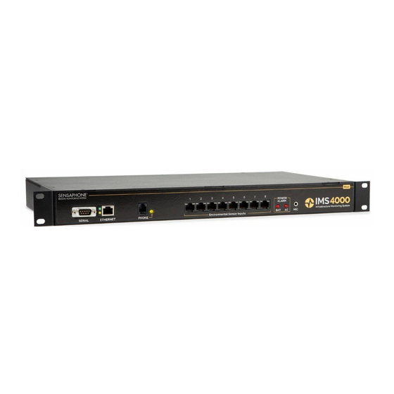
Chapter 1: Installation HOST INSTALLATION and CONFIGURATION Physical Description The IMS-4000 Host is housed in a 17"w x 1.75"h x 10"d enclosure, which is 1 EIA rack-mount space high. Front Panel Layout The front panel contains connections for eight sensor inputs, microphone input, Ethernet port, serial port, and status LEDs. -
Page 28: Sensor Inputs
IMS-4000 Manual Sensor Inputs The sensor inputs are designed to interface with IMS-4000 series sensors (See Chapter 7). The use of RJ-45 jacks for sensor inputs allows the use of existing structured cabling to connect remote sensors. Since the sensor produces an analog signal, it must connect directly to the Host or Node. The path from the sensor to the IMS unit CANNOT pass through a network Hub or Switch. -
Page 29: Rear Panel
Requires 1.0 EIA rack mount space. Tabletop requirements: Flat area which can support an enclosure 17" wide by 10" deep by 2" high. Rack Mount Installation The IMS-4000 Host can be rack mounted using the included rack mount brackets. Follow the steps below:... -
Page 30: Wall Mount Installation
The IMS-4000 Host can be wall mounted using the optional wall mount brackets. Follow the steps below: 1) Attach the optional wall mount brackets to the sides of the IMS-4000 using the eight black #6-32 screws. A Phillips screwdriver will be required. (Order part # IMS-4406 Universal Wall Mount Kit) 2) Attach the unit to the wall using two screws per side. -
Page 31: Power On Self Test (Post)
For example: Suppose you have an IMS-4000 installed in room A and you want to install a sensor in room B. If your existing cabling infrastructure has an unused cable path between room A and room B, then you simply use an RJ-45 interconnect cable to connect the IMS-4000 to the patch panel in room A, and an RJ-45 intercon- nect cable from the wall jack in room B to the sensor. - Page 32 IMS-4000 Manual Sensaphone IMS-4000 Host Unit V1.0.0.0 Enter Password ()> {The dEfaUlT PaSSword for a New Unit is “ims4k”} 1. display Enterprise status 2. display Network and option configuration 3. Configure Network settings 4. Configure Enterprise Name 5. Configure web Server 6.
- Page 33 Option 6 allows you to configure the RAS (Remote Access Server). This can be used to provide remote access to your network via a dial-up connection to the IMS-4000 Host. Note that there are serious security risks associated with enabling this feature. A sample of the RAS menu is shown...
-
Page 34: Local Configuration Definitions
The default password in a new unit is “ims4k.” IP: This is the IP address assigned to the IMS-4000 on your network. This address is provided by you or your network administrator. It is formatted as a standard dotted decimal number. -
Page 35: Battery Maintenance
The IMS-4000 Host includes an internal UPS that automatically switches to battery backup in the event of an AC power failure. The battery in the IMS-4000 Host is a 12V 2.9AH gel cell. This bat- tery will keep the unit operating for approximately 3.5 hours when fully charged and under normal operating conditions. - Page 36 THERE IS A RISK OF ELECTRICAL SHOCK UNLESS YOU DISCONNECT THE CORD . Figure 6: Battery location Step 1) Locate the power switch on the rear of the unit and turn the IMS-4000 off. Step 2) Disconnect the power cord from the back of the unit. Step 3) Disconnect the phone line from the front of the unit.
-
Page 37: Akkumulator Austauschen
Schritt 10) Den Anschluss mit dem roten Leiter am Pluspol des Akkumulators anschließen. Schritt 11) Den Anschluss mit dem schwarzen Leiter am Minuspol des Akkumulators anschließen. Schritt 12) Die obere Abdeckung des IMS-4000 wieder aufsetzen und mit den Schrauben befestigen. Schritt 13) Das IMS-4000 wieder in das Rack einbauen. -
Page 38: Ims Host Specifications
IMS-4000 Manual IMS Host Specifications Operating Specifications Temperature 32–122° F Humidity 5–90% RH non-condensing Power Supply 100–250VAC 50–60Hz Power Consumption (Typ) 25 Watts Power Connection IEC 320 Dimensions 1.75"h x 9.5"d x 19"w Backup Battery 12V 2.9AH Sealed Gel Cell Backup Time 3.5 Hours... -
Page 39: Node Installation & Configuration
Chapter 1: Installation NODE INSTALLATION & CONFIGURATION Physical Description The IMS-4000 Node is housed in a 9.6"w x 1.75"h x 7"d enclosure, which is 1 EIA rack-mount space high. Front Panel Layout The front panel contains connections for eight sensor inputs, microphone input, Ethernet port, serial port, and power LED. -
Page 40: Rear Panel
Screwdriver modem cable w/DB9 serial port Operating Environment Before you install the IMS-4000 Node be sure that your operating environment meets the physical requirements of the equipment. Operating Temperature: 32º– 122º Fahrenheit (0º – 50º C) Humidity: 5 –90 %RH, non-condensing... -
Page 41: Rack Mount Installation
(Größe C, 2000 mAh). Wenn Sie einen solchen Knoten verwenden, müssen Sie die alten Akkumulatoren durch neue Nickelkadmium-Akkumulatoren der Größe C ersetzen. Rack Mount Installation The IMS-4000 Node can be rack mounted using the included rack mount brackets. Follow the steps below: 1) Attach rack-mount brackets to the Node with a Phillips screwdriver. -
Page 42: Wall Mount Installation
The IMS-4000 Node can be wall mounted using the optional wall mount brackets. Follow the steps below: 1) Attach the optional wall mount brackets to the sides of the IMS-4000 using the eight black #6-32 screws. A Phillips screwdriver will be required. (Order part # IMS-4406 Universal Wall Mount Kit) 2) Attach the unit to the wall using two screws per side. -
Page 43: Connecting Sensors
For example: Suppose you have an IMS-4000 Node installed in room A and you want to install a sensor in room B. If your existing cabling infrastructure has an unused cable path between room A and room B, then you simply use an RJ-45 interconnect cable to connect the IMS-4000 Node to the patch panel in room A, and an RJ-45 interconnect cable from the wall jack in room B to the sensor. -
Page 44: Local Configuration Definitions
Option 7 will logout without rebooting. Local Configuration Definitions Parent Host IP Address: This is the IP address of the IMS-4000 Host that this Node is associated with. Node IP Address: This is the IP address assigned to the IMS-4000 on your network. This address is provided by you or your network administrator. - Page 45 DNS Server: The DNS server is used to translate site names into actual numeric network addresses. Enter the IP address of the DNS server for your network. Node Name: This name will appear in the IMS-4000 ConsoleView Software. In systems with many Nodes, the Name is useful for identifying one node from another.
-
Page 46: Node Specifications
IMS-4000 Manual Node Specifications Operating Specifications Temperature 32–122° F Humidity 5–90% RH non-condensing Power Supply 120VAC 60Hz Power Consumption 10 Watts Dimensions 1.8"h x 7.0"d x 9.6"w Backup Battery (1) 6V 3.4AH sealed rechargeable Backup Time 3.5 Hours Communications Specifications... -
Page 47: Chapter 2: Ims-4000 Software
Figure 1: Add Group Right-click on the words IP Unknown below the enterprise name and select Set IP Address. Enter the IP address for your IMS-4000 Host and click OK. The software will prompt you for a username and password to log in. -
Page 48: Configure The Unit Properties For The Host And Node(S)
Most Alphanumeric pagers work best when set to 1200bps. The Host can synchronize its clock each night to a time server. To use this feature the IMS-4000 must have network access to a server which supports one of the following: Network Time Protocol - NTP (RFC-1035), Time Protocol - TP (RFC-868), or Daytime Protocol - DP (RFC-867). -
Page 49: Configure Ip Alarms
Chapter 2: Software up alarm contact information, right-click on the profile name and select Add New Contact. You can have up to eight contacts per user. The User Profile screen is shown below: Figure 3: User Profile Configure IP Alarms Program the IP addresses for each network device you want to monitor. -
Page 50: Software Installation And Hardware Requirements
IMS-4000 Manual Software Installation and Hardware Requirements This section describes how to install and configure the IMS-4000 ConsoleView Software for your enterprise. Hardware and Software Requirements Minimum Requirements: Intel Pentium processor or equivalent 30 MB of free disk space 32 MB of RAM (64 MB RAM recommended) -
Page 51: Starting The Ims-4000 Consoleview Software
Right-click on the words IP Unknown below the enterprise name and select Set IP Address. Enter the IP address for your IMS-4000 Host and click OK. The software will prompt you for a username and password to log in. For new units, the default username is admin and the default password is... -
Page 52: Connecting To A Host
IMS-4000 Manual ims4k. The software will now attempt to connect to your IMS-4000 Host. A progress bar will show the software retrieving information from the Host. Default Username: admin Default Password: ims4k Note: Do not save the default username and password, because it will be deleted automatically once a Master System Administrator profile is configured. -
Page 53: Setting The Unit Properties For The Ims Host
Chapter 2: Software Setting the Unit Properties for the IMS Host To set the global properties of your IMS-4000, right-click on the Host name and select Unit Properties. On the System Info tab, enter the Unit Name, Description and Location. These param- eters will be used when sending alarms to identify the unit. -
Page 54: Adding A Node
The IMS-4000 can be programmed to synchronize its clock to a reference time server every night at midnight. To use this feature the IMS-4000 must have network access to a server which supports one of the following time code protocols:... -
Page 55: Deleting A Node
IP address. Setting the Unit Properties for the Node To set the Properties of your IMS-4000 Node, right-click on the Node name and select Node Properties. The Node Name will be copied from the node itself as programmed during the network configuration procedure. -
Page 56: Sample Application
IMS-4000 Manual In normal operation information is periodically passed between the Node and Host. This informa- tion mainly consists of current Input values and IP Alarm status. The amount of data transferred during this update is about 700 bytes. You can choose how often information is updated from the Node by selecting either periodic updates (Auto Send) or by selecting Update on a Percent Change basis. -
Page 57: Configuring Environmental Inputs
Chapter 2: Software Figure 15: Node Network Settings NOTE: If the Modify button is grey (inactive) then the unit either does not have the Allow Remote Configuration option set, or the unit’s firmware does not support this feature and requires upgrading. Enter the new network parameters and click OK. -
Page 58: Editing The Schedule
In Use: This indicates that a valid sensor is plugged into the channel. Enabled: This indicates if the channel is currently enabled for alarm monitoring. If it is disabled, the IMS-4000 will not send alarm messages. A channel can be enabled or disabled based on a 7- day + holiday time schedule. - Page 59 Custom Voice: Click the drop down arrow and select the custom voice message you would like assigned to this sensor/channel. Voice messages can be recorded on your PC and uploaded into the IMS-4000 on the Custom Voice Manager screen (See Recording and Uploading Voice Messages).
-
Page 60: Alarm Response Via The Powergate, Powergate2, Or Camera
IMS-4000 Manual Alarm Response via the PowerGate, PowerGate2, or Camera PowerGate When an alarm occurs, you can have PowerGate or PowerGate2 outlets automatically turn ON, turn OFF, or CYCLE power to a device. Cycling will switch an outlet OFF for 10 seconds and then switch it back ON. -
Page 61: High Sound Alarms
Contact Schedule. High Sound Alarms The IMS-4000 measures the sound level with the built-in microphone on the front panel. This can be useful in detecting audible alarms in close proximity to the unit. To detect alarms at a distance from the unit, you can plug an external condenser microphone into the mic jack. Note that the audible alarm must be more than just a periodic beep. -
Page 62: Environmental Input Alarm Logic
Trouble Alarms The IMS-4000 monitors the presence of all connected sensors to insure the reliability of the system. When a sensor is removed from a Host or Node for more than a minute, a trouble alarm is gener- ated. - Page 63 Chapter 2: Software configure the Templates, click the plus box next to the word Settings to expand the options under this heading. Next, expand the Input Templates. This will list all of the different sensor types. Figure 24: Template Types Right-click on each of the sensor names to bring up the individual Template programming screens.
-
Page 64: Configuring Ip Alarms
Enabled: This indicates if the IP Address is currently enabled for alarm monitoring. If it is disabled, the IMS-4000 will not send alarm messages. An IP Alarm can be enabled or disabled based on a 7-day + holiday time schedule. - Page 65 IMS-4000 on the Voice screen. Reset Time: This is the time allowed for an acknowledged alarm’s fault condition to be corrected before the IMS-4000 resets (reactivates) the alarm and begins the message delivery process all over again. The minimum reset time is 30 minutes.
-
Page 66: Alarm Logic
Once a successful response is received, the failure counter will reset. For example: If the ping Retries is set to 3, then the IMS-4000 must fail to ping/connect to the device 4 times in a row (initial attempt + 3 retries) to trip an alarm. If the device were to respond after the second attempt, then the failure counter would reset, thus requiring four subsequent successive failures to trip an alarm. -
Page 67: Removing An Ip Alarm
Chapter 2: Software Figure 28: IP Alarm Flowchart Removing an IP Alarm Expand the IP Alarms and right-click on the IP Alarm you wish to remove. Choose Delete this IP Alarm, and it will be removed. -
Page 68: Input/Alarm Classes
Figure 29: Setup Classes You can have up to 64 classes in the IMS-4000. To add Classes, just type in a new class name in the Class table list and click OK. The class programming screen is shown above. Note that the Diagnostic Class does not appear in the list shown above. -
Page 69: Configuring User Profiles And Contacts
When an alarm occurs the IMS-4000 will check the list of User Profiles to see who should be contacted. Users whose class list includes the class of the alarm will be contacted. Each user can have up to 8 contact destinations (phone numbers, e-mail addresses, …). -
Page 70: Permissions
IMS-4000 Manual Clicking the Permissions button will bring up the Permission screen. Permissions Each user profile has a programmable security level for each device (host/nodes) in the system. To set the Security Access level click the Permissions button. There are three access levels: Master System Administrator, Site Administrator, and User. -
Page 71: Classes
Chapter 2: Software Figure 31: Permissions screen To configure profiles for Site Administrator or User security levels, select the appropriate Host or Node(s) and click the arrow to copy the Host/Node(s) into the appropriate list. The double arrow >> will copy all units to the list while the single arrow > will copy just the selected unit to the list. Checking the box “This user can connect remotely via modem”... -
Page 72: Deleting A Profile
The Contacts are the actual telephone numbers, e-mail addresses, pager numbers, etc… that the IMS-4000 will contact when an alarm occurs. You can have up to 8 Contacts per User Profile. Each Contact can have its own Schedule so that you can have certain Contacts be Enabled during daytime hours and others Enabled during nighttime hours. -
Page 73: Voice Calls
For most voice calls you can simply enter the telephone number of the person you want called. Consider the location of the IMS-4000 Host when entering the number. If an area code is required to call from the Host to your telephone, be sure to include it. -
Page 74: Fax Calls
Once the alarm message has been delivered, the IMS will stop calling this contact. This selection is useful for insuring that a record of an alarm is sent. When this option is checked, the IMS-4000 will always send an alarm message to this contact. -
Page 75: Saving And Loading Programming
Chapter 2: Software Saving and Loading Programming The programming in your IMS-4000 can be saved to a file. This gives you the ability to back up your programming or copy the same programming to another IMS-4000 unit. Note that the file you save will not include custom voice files or settings entered through the serial port (network param- eters, web settings, two-way e-mail, RAS, etc.). -
Page 76: Recording Voice Messages
See the following screen. Figure 38: Sound Specifications screen Next, save this recording format by typing “IMS-4000” in the Name field and click Save As. Click OK on each screen until you get back to the Sound Recorder main screen. -
Page 77: Holiday Setup
IMS-4000 and will appear in the list. The window to the right displays all of the voice message file names stored in the IMS-4000. To change the file name of a voice message click Rename. Enter a new file name and click OK. -
Page 78: Alarm Message Pop-Ups
IMS-4000 Manual Alarm Message Pop-Ups While online with one or more IMS-4000 units through the ConsoleView Software, you can have an alarm message pop up on your computer screen whenever an alarm occurs. This could be an environmental or IP alarm on any Host or Node. You can configure this feature to display a general message indicating the Unit and Channel names, or you can associate a custom message with each input. -
Page 79: Enabling Custom Pop-Up Messages
Chapter 2: Software Enabling Custom Pop-Up Messages To have custom messages pop up, you must enable this feature. Select Options from the main menu. Click in the box labeled Include Custom Message with Alarm Pop-Ups. Next, you must select where your custom messages will be stored (see below). Setting Pop-Up Text Location When using custom pop-up messages you must specify where these messages will be located. -
Page 80: Audible Alarm Notification
Return Address programmed. These are the minimum programming requirements to send e- mail. If you have at least these two items programmed and the IMS-4000 is unable to deliver the message, then you will get the message “SMTP Server not Responding,” which essentially means... -
Page 81: Two Way E-Mail
IMS-4000. A set of commands is available that can be sent to a 4000, within an e-mail, that will cause the 4000 to reply back to the sending e-mail address. Commands are available to inquire status, perform network ping and IP trace-route, and control outlets on a PowerGate. -
Page 82: Requesting A Trace Route
IMS-4000 Manual Requesting a Trace Route To request an IP trace-route, send an e-mail message to your IMS-4000 Host with the following information: To: <e-mail address of your IMS-4000> Subject: ims4000 username: <valid profile username> email: <your e-mail address> command: traceroute xxx.xxx.xxx.xxx... -
Page 83: Requesting Help
Capture Image. The first step is to get the camera running on your network. This process is independent of the IMS-4000. Follow the instructions included with the camera to get it set up. Once the camera is... - Page 84 IMS-4000 Manual properly set up, go into the IMS-4000 ConsoleView Software. Cameras are added to the IMS by expanding the Settings menu and right-clicking on the word Cameras. Choose Add Camera. This will bring up the Camera Setup screen (see below). Enter the IP address, port number, and security settings (if required) of the camera according to how it has been configured on your network.
-
Page 85: Web Page
Chapter 2: Software Web Page The IMS-4000 will produce a web page which includes: • The status of all Environmental Inputs and IP Alarms. • The ability to program most parameters. • Links to view logged data for each Input and IP alarm. -
Page 86: Updating The Web Page
Figure 51: Web Page Refresh Enabled Remote Web Page The IMS-4000 can send a copy of its web page to another web server via FTP (File Transfer Protocol), so that the web page can be viewed on another network (for example, on the Internet). -
Page 87: Viewing The Remote Web Page
Viewing the Remote Web Page To view the remote web page that the IMS-4000 uploaded, you need to know its web address. This address corresponds to the Server name, plus the directory, plus the file name of the web page. It will look something like this: http://www.mycompany.com/jwilson/ims4k.html... -
Page 88: History
The eventlog history is useful when you want to review the historical events monitored and performed by the IMS-4000. When a user goes online, information for both the datalog and eventlog history is automatically retrieved and stored in a database on a user-specified hard disk. -
Page 89: Datalog History
Chapter 2: Software Datalog History The IMS-4000 can log up to 62,500 samples of environmental and IP Alarm history. When the log fills, it will overwrite the oldest data first. Environmental data will display the actual value, while IP Alarm data will display either Normal, Timed Out, or IP Down. All stored history is logged at the same interval as programmed on the History programming screen. -
Page 90: Graphing
IMS-4000 Manual To begin, run the HistoryView program by right-clicking on History in the menu tree and select HistoryView, or from the main menu select File, then HistoryView. The first screen will prompt you to select an IMS Host. Click in the box next the Host you want to Query. The program will then load the associated nodes and input names. -
Page 91: Printing Data
Chapter 2: Software Printing Data You can print the data viewed in the grid by clicking the Print button. Printing defaults to an Arial 5 pt. font in order to fit one line of data across one line of an 8.5" x 11" sheet of paper printed in landscape mode. -
Page 92: Manually Forcing History Downloads
From time to time Firmware updates will become available to add features or improve the perfor- mance of your IMS-4000. Most Firmware updates will be included as part of a complete IMS- 4000 installation upgrade. Check the IMS-4000 website (www.sensaphone.com/support-4000.html) for the latest information on updates. -
Page 93: Chapter 3: Operation
This chapter explains how the IMS-4000 operates. Alarm Delivery and Acknowledgment The IMS-4000 can be programmed to contact specific users when an alarm occurs. A user may be contacted depending on whether the alarm has already been acknowledged by another user, or regardless of acknowledgement by other users. -
Page 94: Alarm Delivery Logic
Figure 2: Web page acknowledgment 5) By SNMP Management software. 6) By the IMS-4000 itself. If there are no Until Acknowledge contacts in the call list or if the maximum number of calling rounds has been exhausted, the IMS-4000 will self-acknowledge the alarm. -
Page 95: Sample Fax Message
Thursday 28 March 2002, 10:24:32 aM EST Voice Status Report and Touch-Tone Commands The IMS-4000 is capable of delivering a spoken status report when called via telephone. The status report can provide information on both environmental conditions and IP alarms. In addition, you can ping devices over the telephone and switch PowerGate outlets. -
Page 96: Sample Status Report
User has no Environmental sensors in his class, then these will be skipped. Voice Alarm Dialout The IMS-4000 can call and deliver an alarm message in spoken English. After dialing, the unit will begin speaking “IMS-4000 Alarm Message, Press any key to continue.” If the unit receives a touch-tone, it will recite the alarm message. -
Page 97: Performing An Ip Ping Via Telephone
Performing an IP Ping via Telephone The IMS-4000 allows you to perform an IP Ping during a voice call-in to the Host. After dialing the unit, press a touch-tone after the beep. The unit will request your User Code. Next, listen to the menu choices. -
Page 98: Windows 2000
For the Network Connection Type choose Dial-up to Private Network. Enter the telephone number of your IMS unit and assign a name to the connection (“IMS-4000,” for example). When prompted to enter your Username and Password be sure to enter information which matches a Profile Username and Password in your IMS-4000. -
Page 99: Chapter 4: Snmp (Simple Network Management Protocol)
The IMS-4000 Host contains an SNMP agent that supports all three current versions of SNMP (v1, V2c, and V3), over both UDP and TCP transports. Read and write access to most of the IMS-4000 parameters is provided along with the ability to send traps when alarms occur. A complete SNMPv1 MIB is provided on the IMS-4000 CD. - Page 100 Object Identifier (OID), which usually has a name in the form of numbers separated by periods (“.”), like this: .1.3.6.1.x.x.xxxx.x.x.x.x... OIDs for all MIB variables can be determined by browsing the MIB. Below are some examples of the more common OIDs in the IMS-4000: Name: .iso.org.dod.internet.private.enterprises.sensaphone Sensaphone OID: .1.3.6.1.4.1.8338 Host Environmental Input Values: .1.3.6.1.4.1.8338.1.1.1.1.8.1.1.7.(input number)
-
Page 101: Chapter 5: Powergate
Chapter 5: PowerGate Chapter 5: PowerGate Physical Description The IMS-4000 PowerGate is housed in a 17"w x 1.75"h x 10"d enclosure, which is 1 EIA rack- mount space high. Front Panel Layout The front panel contains a 15 Amp breaker, Output LEDs, the serial port and power indicator. See... -
Page 102: Parts Required
IMS-4000 Manual Parts Required Phillips 9 pin F/F null Screwdriver modem cable Operating Environment Before you install the IMS-4301 PowerGate be sure that your operating environment meets the physical requirements of the equipment. Operating Temperature: 32º– 95º Fahrenheit (0º –35º C) Humidity: 5 –... -
Page 103: Connection To Ims-4000 Host Or Node
Figure 4: Tabletop-mounted PowerGate Unit Connection to IMS-4000 Host or Node The PowerGate connects to an IMS-4000 Host or Node using the 9-pin null modem cable (included). Connect the cable to the RS-232 port on the PowerGate and connect the other end to the RS-232 port on the Host or Node. -
Page 104: Switching Outlets Using The Ims Consoleview Software
IMS-4000 Manual Figure 6: PowerGate in Hierarchy To assign labels to the PowerGate, right-click on PowerGate. The following screen will appear: Figure 7: PowerGate Setup Assign a name to the PowerGate that describes its location. Also, assign labels to each outlet which describes the device plugged into that outlet. -
Page 105: Automatic Outlet Switching
Alarms in the IMS-4000 Software Configuration Manual for details. Switching Outlets via Telephone The IMS-4000 allows you to switch PowerGate outlets using a touch-tone telephone. To do this simply call the unit and enter the voice menu system. You must have a valid user code and the appropriate permissions to execute this command. -
Page 106: Ims Powergate Specifications
IMS-4000 Manual IMS PowerGate Specifications Operating Specifications Temperature 32–95° F (0-35°C) Humidity 5–90% RH non-condensing Power Supply 120VAC 60Hz Current Consumption 100mA + output load (12A Max) Over-Current Protection 15A Breaker Dimensions 1.8"h x 10.0"d x 17.3"w... -
Page 107: Chapter 6: Powergate2
Chapter 6: PowerGate2 Chapter 6: PowerGate2 Physical Description The IMS-4000 PowerGate2 is housed in a 17.5"w x 1.75"h x 12.3"d enclosure, which is 1 EIA rack-mount space high. Front Panel Layout The front panel contains eight power inputs corresponding to the eight outlets on the rear, eight 15 Amp breakers, power LEDs, a serial port and one power indicator LED. -
Page 108: Installation
IMS-4000 Manual Installation This section provides information on: n Operating environment n Rack and tabletop installation Parts Required Phillips 9 pin F/F null Right-angle input Screwdriver modem cable power cable (1 included)* *For additional right-angle power input cables, order part # IMS-4413. -
Page 109: Tabletop Installation
Connection to IMS-4000 Host or Node The PowerGate2 connects to an IMS-4000 Host or Node using the 9-pin null modem cable (includ- ed). Connect the cable to the RS-232 port on the PowerGate2 and connect the other end to the RS- 232 port on the Host or Node. -
Page 110: Connect Input Power
IMS-4000 Manual Connect Input Power Attach a power cable to a power input on the front of the PowerGate2 and plug the other end into a 120VAC 15A outlet or into an outlet on your PDU. One right-angle power cable is included. -
Page 111: Latched Power To Outlets
Chapter 6: PowerGate2 Latched Power to Outlets The PowerGate2 design features latching power circuits. Each outlet remains latched ON as long as power is applied to the corresponding input. This holds true even if main power to the unit is removed. -
Page 112: Automatic Outlet Switching
Figure 10: Switching Outlets Automatic Outlet Switching The IMS-4000 allows you to program an Alarm Response whenever an environmental or IP Alarm occurs. An Alarm Response is an action that occurs automatically whenever an alarm occurs. Using the PowerGate2 you can automatically turn On, Off, or Cycle equipment whenever an Environmental or IP alarm occurs. -
Page 113: Ims Powergate2 Specifications
Chapter 6: PowerGate2 IMS PowerGate2 Specifications Operating Specifications Main Power Supply 120VAC 50/60Hz, 1 Amp Main Power Cord 9' Cable with NEMA 5-15P plug Channel Input Power 120VAC 50/60Hz, 12 Amp max. Channel Input Connectors (8) IEC60320 Type C14 Channel Circuit Breakers (8) 15Amp Channel Output Power 120VAC 60Hz, 12 Amp max. -
Page 114: Chapter 7: Ims-4000 Sensors
" hex key Cabling The temperature sensor connects to the IMS-4000 Host or Node via an RJ-45 cable (e.g. CAT5 cable). The connection from the sensor to the Host or Node can utilize your existing network wir- ing infrastructure. For example, the sensor may be installed in another room or another floor. -
Page 115: Hidden Cable Surface Installation
Chapter 7: IMS-4000 Sensors using the appropriate screws. Secure the sensor cover by turning the two hex screws on the bottom of the cover counterclockwise. Figure 1: 4810 with Cable exiting through back of enclosure Hidden cable surface installation Bring the RJ-45 cable through the wall at the mounting location. Remove the sensor cover by turn- ing the two hex screws on the bottom of the sensor housing clockwise. -
Page 116: Configuration
IMS-4000 Manual Figure 2: 4810 with Cable exiting out enclosure bottom Configuration All IMS Solution sensors are auto-configured when you plug them into the Host or Node. When a new sensor is plugged into the Host or Node, the configuration is set to the factory default via the Sensor Template. -
Page 117: Sensor Template (Factory Default)
Chapter 7: IMS-4000 Sensors Sensor Template (factory default) Input Name: Temperature Low Temperature Limit: 50º F High Temperature Limit: 85º F Recognition Time: 60 Seconds Reset Time: 0 Seconds Data Logging: Active Voice: temperature.wav Input Class: Temperature Specifications Range: 5–122 degrees F (-15 to 50 degrees C) Humidity: 5–90 %RH... -
Page 118: Ims-4811 Room Temperature Sensor With Display (Fahrenheit)
" hex key Cabling The temperature sensor connects to the IMS-4000 Host or Node via an RJ-45 cable (e.g. CAT5 cable). The connection from the sensor to the Host or Node can utilize your existing network wiring infrastructure. For example, the sensor may be installed in another room or another floor. Connect the sensor to your structured wiring network via an RJ-45 jack. -
Page 119: Hidden Cable Surface Installation
Chapter 7: IMS-4000 Sensors Figure 1: 4811 with Cable exiting through back of enclosure Hidden cable surface installation Bring the RJ-45 cable through the wall at the mounting location. Remove the sensor cover by turn- ing the two hex screws on the bottom of the sensor housing clockwise. Bring the cable through the back of the sensor and hold the sensor housing against the wall. -
Page 120: Configuration
IMS-4000 Manual Configuration All IMS Solution sensors are auto-configured when you plug them into the Host or Node. When a new sensor is plugged into the Host or Node, the configuration is set to the factory default via the Sensor Template. If you have modified these templates, the configuration will be set to the modi- fied configuration. -
Page 121: Ims-4812 Mini-Temperature Sensor (Fahrenheit)
The Mini-Temperature Sensor comes with an attached 7' cable with an RJ-45 plug on the end. If the sensor is close to the IMS-4000 Host or Node, you can plug the sensor directly to an IMS environ- mental input. If the cable is too short you can use the included RJ-45 adaptor and a longer patch cable to extend the length. -
Page 122: Sensor Template (Factory Default)
IMS-4000 Manual Sensor Template (factory default) Input Name: Temperature Low Temperature Limit: 50º F High Temperature Limit: 85º F Recognition Time: 60 Seconds Reset Time: 0 Seconds Data Logging: Active Voice: temperature.wav Input Class: Temperature Specifications Range: 5–140 degrees F Humidity: 5–90% RH... -
Page 123: Ims-4813 Room Temperature Sensor With Display (Celsius)
" hex key Cabling The IMS-4813 temperature sensor connects to the IMS-4000 Host or Node via an RJ-45 cable (e.g. CAT5 cable). The connection from the sensor to the Host or Node can utilize your existing network wiring infrastructure. For example, the sensor may be installed in another room or another floor. -
Page 124: Hidden Cable Surface Installation
IMS-4000 Manual Figure 1: 4813 with Cable exiting through back of enclosure Hidden cable surface installation Bring the RJ-45 cable through the wall at the mounting location. Remove the sensor cover by turn- ing the two hex screws on the bottom of the sensor housing clockwise. Bring the cable through the back of the sensor and hold the sensor housing against the wall. -
Page 125: Configuration
Chapter 7: IMS-4000 Sensors Configuration All IMS Solution sensors are auto-configured when you plug them into the Host or Node. When a new sensor is plugged into the Host or Node, the configuration is set to the factory default via the Sensor Template. -
Page 126: Ims-4814 Ultra Low Temperature Sensor
7' cable with an RJ-45 plug on the end and a weatherproof probe with 12' of cable. If the sensor installation is close to the IMS-4000 Host or Node, you can plug it directly into an IMS environmental input. If the cable is too short you can use the included RJ-45 adaptor and a lon- ger patch cable to extend the length. -
Page 127: Host And Node Firmware Requirements
Host and Node Firmware Requirements The Ultra Low Temperature Sensor requires the following firmware versions in the IMS-4000 Host and updated ConsoleView software for your computer for sensor compatibility: IMS-4000 Host •... -
Page 128: Ims-4820 Room Humidity Sensor
" hex key Cabling The humidity sensor connects to the IMS-4000 Host or Node via an RJ-45 cable (e.g. CAT5 cable). The connection from the sensor to the Host or Node can utilize your existing network wiring infra- structure. For example, the sensor may be installed in another room or another floor. Connect the sensor to your structured wiring network via an RJ-45 jack. -
Page 129: Hidden Cable Surface Installation
Chapter 7: IMS-4000 Sensors Figure 1: 4820 with Cable exiting through back of enclosure Hidden cable surface installation Bring the RJ-45 cable through the wall at the mounting location. Remove the sensor cover by turn- ing the two hex screws on the bottom of the sensor housing clockwise. Bring the cable through the back of the sensor and hold the sensor housing against the wall. -
Page 130: Configuration
IMS-4000 Manual Configuration All IMS Solution sensors are auto-configured when you plug them into the Host or Node. When a new sensor is plugged into the Host or Node, the configuration is set to the factory default via the Sensor Template. If you have modified these templates, the configuration will be set to the modi- fied configuration. -
Page 131: Ims-4821 Room Humidity Sensor With Display
(1) 1/16" hex key Cabling The humidity sensor connects to the IMS-4000 Host or Node via an RJ-45 cable (e.g. CAT5 cable). The connection from the sensor to the Host or Node can utilize your existing network wiring infra- structure. For example, the sensor may be installed in another room or another floor. Connect the sensor to your structured wiring network via an RJ-45 jack. -
Page 132: Hidden Cable Surface Installation
IMS-4000 Manual Figure 1: 4821 with Cable exiting through back of enclosure Hidden cable surface installation Bring the RJ-45 cable through the wall at the mounting location. Remove the sensor cover by turn- ing the two hex screws on the bottom of the sensor housing clockwise. Bring the cable through the back of the sensor and hold the sensor housing against the wall. -
Page 133: Configuration
Chapter 7: IMS-4000 Sensors Configuration All IMS Solution sensors are auto-configured when you plug them into the Host or Node. When a new sensor is plugged into the Host or Node, the configuration is set to the factory default via the Sensor Template. -
Page 134: Ims-4830 Water Detection Sensor
(4) Rubber feet Cabling The water detection sensor connects to the IMS-4000 Host or Node via an RJ-45 cable (e.g. CAT5 cable). The connection from the sensor to the Host or Node can utilize your existing network wir- ing infrastructure. For example, the sensor may be installed in another room or another floor. -
Page 135: Cascading Water Sensors
Chapter 7: IMS-4000 Sensors Cascading Water Sensors You can cascade up to three Water Detection Sensors from a single IMS input channel. This is use- ful if there is a large distance between each sensor and you don’t want to use up additional IMS inputs for individual sensors. -
Page 136: Sensor Template (Factory Default)
IMS-4000 Manual the sensor is plugged in again, or the connection is re-established, configuration data remains unchanged and the sensor returns to normal operating condition. Caution: Removing a sensor for less than 60 seconds does not produce a trouble alarm. -
Page 137: Ims-4840 External Power Sensor
(4) Rubber feet Cabling The Power Sensor connects to the IMS-4000 Host or Node via an RJ-45 cable (e.g. CAT5 cable). The connection from the sensor to the Host or Node can utilize your existing network wiring infra- structure. For example, the sensor may be installed in another room or another floor. Connect the sensor to your structured wiring network via an RJ-45 jack. -
Page 138: Mounting
IMS-4000 Manual Mounting The sensor can be mounted to a wall or lie flat on the floor. To mount the sensor to a wall, install the two drywall anchors (if necessary) and attach the Power Sensor using the two #6 tapping screws. -
Page 139: Sensor Template (Factory Default)
Chapter 7: IMS-4000 Sensors Sensor Template (factory default) Input Name: Power Low Limit: 90VAC High Limit: 130VAC Recognition Time: 60 Seconds Reset Time: 0 Seconds Data Logging: Active Voice: power default.wav Input Class: Power Specifications Range: 0–250 VAC, 50/60 Hz Accuracy: ±... -
Page 140: Ims-4841 15A High Current Sensor
IEC320 C14 inlet and C13 outlet connectors. Cabling The Current Sensor connects to the IMS-4000 Host or Node via an RJ-45 cable (e.g. CAT5 cable). The connection from the sensor to the Host or Node can utilize your existing network wiring infra- structure. -
Page 141: Ims-4000 Node
Chapter 7: IMS-4000 Sensors • ConsoleView version 3.0.15 or higher • IMS4K OS version 3.00 or higher • Voice version 2.12 or higher *Host version information is viewable through the ConsoleView software on the Version Info screen and the Help>About selection from the main menu. - Page 142 IMS-4000 Manual Sensor Template (factory default) Input Name: Transducer High Limit: 100 Low Limit: 0 Recognition Time: 60 Seconds Reset Time: 0 Seconds Data Logging: Active Voice: none Input Class: Other Specifications Range: 0–15 Amps (0-250 VAC, 50/60 Hz) Operating Temperature: 5-104°F (-15 to 40°C) Operating Humidity: 0-95% RH, non–condensing...
-
Page 143: Ims-4842 20A High Current Sensor
IEC320 C20 inlet and C19 outlet connectors. Cabling The Current Sensor connects to the IMS-4000 Host or Node via an RJ-45 cable (e.g. CAT5 cable). The connection from the sensor to the Host or Node can utilize your existing network wiring infrastructure. -
Page 144: Ims-4000 Node
IMS-4000 Manual NOTE: Input board firmware is NOT flash upgradeable. A new firmware chip must be installed. For information on obtaining a new firmware chip, please contact Sensaphone Technical Support at 610.558.2700 or via e-mail at support@sensaphone.com. • ConsoleView version 3.0.15 or higher •... -
Page 145: Sensor Template (Factory Default)
Chapter 7: IMS-4000 Sensors Caution: Removing a sensor for less than 60 seconds does not produce a trouble alarm. Removing or unplugging a sensor for more than 60 seconds or plugging in a different sensor at any time will cause a trouble alarm. -
Page 146: Ims-4850 Dry Contact Bridge
Figure 1: Connections to the IMS-4850 Cabling The Dry Contact Bridge connects to the IMS-4000 Host or Node via an RJ-45 cable (e.g. CAT5 cable). The connection from the sensor to the Host or Node can utilize your existing network wiring infrastructure. -
Page 147: Mounting
Chapter 7: IMS-4000 Sensors Caution: The IMS sensors are not TCP/IP devices and therefore should not be connected directly to any wiring infrastructure that is connected to network equipment such as a hub, router, or switch. Sensors use RJ-45 plugs and cables similar to those used with Ethernet devices. -
Page 148: Sensor Template (Factory Default)
Sensor Template (factory default) Input Name: Contact Bridge Recognition Time: 3 Seconds Reset Time: 0 Seconds Data Logging: Active Voice: dry contact.wav Input Class: Other Specifications Input: Normally Open or Normally Closed dry contact Source/Sense Voltage: 14VDC Source/Sense Current: 10mA IMS Connection: RJ-45 Operating Temperature Range:... -
Page 149: Ims-4851 4-20Ma Bridge
Figure 1: 4–20mA transducer wiring to IMS-4851 Terminal Block Cabling The 4-20mA Bridge connects to the IMS-4000 Host or Node via an RJ-45 cable (e.g. CAT5 cable). The connection from the sensor to the Host or Node can utilize your existing network wiring infra- structure. -
Page 150: Mounting
SubType drop down menu, then choose Custom Table Limits. Insert the Low (4mA) and High (20mA) values for your transducer into the Table Low and Table High fields. The IMS-4000 will display the scaled value. You may wish to include the units of measure in the Channel Name field. -
Page 151: Host And Node Firmware Requirements
• Input board firmware chip version xx.xx.xx.103 or higher NOTE: Input board firmware is NOT flash upgradeable. A new firmware chip must be installed. For information on obtaining a new firmware chip, please contact Sensaphone Technical Support at 610.558.2700 or via e-mail at support@sensaphone.com. -
Page 152: Ims-4860 Door Switch
The bridge may be mounted either on a wall or rest on the floor. The switch is mounted to doors or windows you wish to monitor. The electrical connec- tion between the bridge and IMS-4000 is made via RJ-45 patch cable. Package Contents... -
Page 153: Mounting The Bridge
The choice depends on your specific application. Cabling The Door Switch connects to the IMS-4000 Host or Node via an RJ-45 cable (e.g. CAT5 cable) from the bridge. The connection from the bridge to Host or Node can utilize your existing network wiring infrastructure. - Page 154 IMS-4000 Manual Cable/Connector: 7' cable with RJ-45 plug Operating Temperature Range: 32–122 deg F (0-50 degC) Housing: Black plastic Dimesnsions: 2.13" x 0.6" x 1.38" Door Switch: Normality: Normally Closed Dimensions: 2.0" x 0.4" x 0.4" (part with screw terminals)
-
Page 155: Ims-4861 Passive Infrared Detection Sensor
The Passive Infrared Detection Sensor comes with an attached 7' cable with an RJ-45 plug on the end. If the sensor is close to the IMS-4000 Host or Node, you can plug the sensor directly to an IMS environmental input. If the cable is too short you can use the included RJ-45 adaptor and a longer patch cable to extend the length. -
Page 156: Configuration
IMS-4000 Manual Bracket Cover Ceiling Mounting Holes Wire Access Hole Wire Access Slot Wall Mounting Slots Figure 1: Mounting bracket Run all cable wiring to the sensor through either the Wire Access Slot (wall mounted), or the Wire Access Hole (ceiling mounted). -
Page 157: Sensor Template (Factory Default)
Chapter 7: IMS-4000 Sensors Jumper in position 1 (to the right): Jumper setting for a stable environment without air drafts. Jumper in position AUTO (to the left): Setting for a harsh environment. Figure 2: Sensitivity adjustment and jumper locations Sensor Template (factory default) -
Page 158: Ims-4862 Smoke Detector Sensor
The Smoke Detector Sensor comes with an attached 7' cable with an RJ-45 plug on the end. If the sensor is close to the IMS-4000 Host or Node, you can plug the sensor directly to an IMS environ- mental input. If the cable is too short you can use the included RJ-45 adaptor and a longer patch cable to extend the length. -
Page 159: Sensor Template (Factory Default)
Housing dimensions: 6.1'' d x 1.9'' h Technical Support for the IMS-4000 Sensors For questions about installing any of these sensors, please contact your local IMS Solution Reseller or VAR or contact the manufacturer directly at: Phonetics, Inc. -
Page 160: Appendix A: Weekly Testing Procedure
4) If you are using your IMS-4000 to listen for a smoke alarm, then be sure to test the smoke alarm to make sure that the IMS-4000 picks up the audible signal and triggers a high-sound-level alarm. -
Page 161: Appendix B: Troubleshooting
The IMS-4000’s Host or Node’s network settings may be incorrect. Verify the IP address, Gateway, DNS, and Subnet mask settings. l There may be a network IP address conflict. The IMS-4000 Host or Node’s IP address may be the same as another device on your network. - Page 162 Yes. Why won’t my IMS-4000 Host dial out? l Check that you have a Touch-Tone telephone line. The IMS-4000 Host will not be able to dial out if it’s on a Pulse telephone line. l The Contact telephone number may be incorrectly programmed. Verify the telephone numbers. Is a ‘1 +area code’...
-
Page 163: Appendix C: Ims-4000 Accessories
IMS-4000 Room Temperature Sensor w/Display (Fahrenheit) IMS-4812 IMS-4000 Mini-Temperature Sensor IMS-4813 IMS-4000 Room Temperature Sensor w/Display (Celsius) IMS-4814 IMS-4000 Ultra Low Temperature Sensor IMS-4820 IMS-4000 Humidity Sensor IMS-4821 IMS-4000 Humidity Sensor w/Display IMS-4830 IMS-4000 Water Sensor w/10' Water Detection Rope... - Page 164 IMS-4000 15A High Current Sensor IMS-4842 IMS-4000 20A High Current Sensor IMS-4850 IMS-4000 Dry Contact Bridge IMS-4851 IMS-4000 4–20mA Bridge IMS-4860 IMS-4000 Door Switch IMS-4861 IMS-4000 Passive Infrared Motion Detector w/7' RJ-45 Cable IMS-4862 IMS-4000 Smoke Detector w/7' RJ-45 Cable...
-
Page 165: Appendix D: License Agreement For Sensaphone® Ims-4000 Consoleview Software
The copyright of the Software at all times belongs to and remains with Sensaphone. Without prior approval of Sensaphone, no part of the Software may be reproduced, distributed or transmitted in any form or by any means, electronic or mechanical, for any purpose other than stated in the License. All title and copyrights in and to... - Page 166 IMS-4000 Manual incorporated into the Software), and any copies of the Software are owned by Sensaphone (or one or more of its licensors). The Software is protected by copyright laws and international treaty provisions. Therefore, you must treat the Software like any other copyrighted material except that you may make copies of the Software, subject to the limitations set forth herein.
- Page 167 Although the Software is scanned for the known viruses, you should scan the Software for viruses or other defects, prior to installation on your system. Sensaphone does not accept any liability for damage or loss as a result of the installation or use of the Software, including but not limited to any damage or loss resulting from any such viruses or defects.
- Page 168 The installation or use of the Software is deemed acceptance of the terms and conditions contained in the License Agreement. This License Agreement shall be effective and binding upon Sensaphone and you, the end user, upon installation or use of the Software. The term of this Agreement shall commence on the date of installation or use by you and shall continue indefinitely if you remain in compliance with all of the terms and condition set forth herein.
-
Page 169: Appendix E: Returning An Ims Unit For Repair
Appendix E: Returning a Unit for Repair Appendix E: Returning an IMS Unit for Repair In the event that any of your Sensaphone IMS-4000 units does not function properly, we suggest that you do the following: 1) Record your observations regarding the individual unit’s malfunction. -
Page 170: Test Log
IMS-4000 Host Installation Manual Test Log... - Page 171 Appendix F: Test Log...
-
Page 172: Index
IMS-4000 Manual Index FCC Requirements v Firmware Updating 90 Accessories 162–163 Alarm Audible Notification 78 History 86–90 Delivery & Acknowledgment 91–93 Archiving the Database 89 Acknowledgment 91–92 Copying to the Clipboard 89 Alarm Delivery Logic 92–93 Datalog History 87–88 Sample Alarm Messages 92–93... - Page 173 IMS-4811 Room Temperature Sensor with display (F) 115–117 Specifications 44 Cabling 116 Configuration 118 Mounting 116–117 PowerGate Specifications & Defaults 118 Connection to IMS-4000 Host or Node 101 IMS-4812 Mini-Temperature Sensor (F) 118–119 Front Panel Layout 99 Cabling 119 LEDs 99 Configuration 119 Installation 99–101...
- Page 174 User Profiles and Contacts Configuring 46–47 Video Camera Configuring 81–82 Voice Messages Record & Assign 47 Recording 74–75 Recording & Uploading 73–75 Voice Status Report & Touch-Tone Commands 93–95 Call-in Alarm Acknowledgment 95 Communicating with your IMS-4000 96 Remote Login via Dialup 95–96...
Need help?
Do you have a question about the IMS-4000 and is the answer not in the manual?
Questions and answers