Table of Contents
Advertisement
Advertisement
Table of Contents

Related Manuals for Sensaphone IMS-1000


Summary of Contents for Sensaphone IMS-1000
- Page 1 SENSAPHONE ® IMS- 1000 User’s Manual Version 1.4...
- Page 2 Every effort has been made to ensure that the information in this document is complete, accurate and up-to-date. Sensaphone assumes no responsibility for the results of errors beyond its control. Sensaphone also cannot guarantee that changes in equipment made by other manufacturers, and referred to in this manual, will not affect the applicability of the information in this manual.
- Page 3 • Read and follow all warning and instruction labels on the product itself. • To protect the IMS-1000 from overheating, make sure all openings on the unit are not blocked. Do not place on or near a heat source, such as a radiator or heat register.
- Page 4 5. Remove main power and telephone connections before replacing the battery. Wichtige Sicherheitshinweise Ein wesentlicher Aspekt bei der Entwicklung Ihres IMS-1000 war die Gewährleistung eines sicheren und zuverlässigen Betriebs über viele Jahre hinweg. Wie bei allen elektrisch betriebenen Einrichtungen sollten Sie jedoch auch hier einige grundlegende Vorsichtsmaßnahmen beachten, um Schäden am Gerät und Verletzungen zu vermeiden: •...
- Page 5 3. Das Gerät wurde fallengelassen oder das Gehäuse ist beschädigt. 4. Das Gerät funktioniert trotz Beachtung der Betriebsanleitung nicht einwandfrei. • Während eines Gewitters kein schnurgebundenes Telefon verwenden. Es besteht Stromschlagrisiko durch Blitzeinschlag. • Gasaustritt niemals telefonisch melden, wenn Sie sich in unmittelbarer Umgebung des Gaslecks befinden.
-
Page 6: Fcc Requirements
IMS-1000 Manual FCC Requirements Part 68: The Sensaphone IMS-1000 complies with 47 CFR, Part 68 of the rules. On the back of the unit there is a label that contains, among other information, the Certification Number and the Ringer Equivalence Number (REN) for this equipment. You must, upon request, provide this information to your local telephone company. -
Page 7: Telephone Consumer Protection Act
Ringer Equivalence Numbers of all the devices does not exceed 5.0. For IMS-1000, the Ringer Equivalence Number is 0.0. - Page 8 Although their code does not appear in gd 2.0.4, the authors wish to thank David Koblas, David Rowley, and Hutchison Avenue Software Corporation for their prior contributions. The following Copyright applies to the Web Server operating within the IMS-1000. Copyright ©2007 GoAhead Software, Inc. All Rights Reserved.
-
Page 9: Year Limited Warranty
THIS LIMITED WARRANTY CONTAINS SENSAPHONE’S STANDARD TERMS AND CONDITIONS. WHERE PERMITTED BY THE APPLICABLE LAW, BY KEEPING YOUR SENSAPHONE PRODUCT BEYOND THIRTY (30) DAYS AFTER THE DATE OF DELIVERY, YOU FULLY ACCEPT THE TERMS AND CONDITIONS SET FORTH IN THIS LIMITED WARRANTY. - Page 10 State of Delaware, without regard to the principles of conflicts of law. Effective date 05/01/2004 PHONETICS, INC. d.b.a. SENSAPHONE 901 Tryens Road Aston, PA 19014 Phone: 610.558.2700 Fax: 610.558.0222...
-
Page 11: Table Of Contents
Table of Contents Table of Contents Important Safety Instructions ..iii Wichtige Sicherheitshinweise....iv FCC Requirements ........Telephone Consumer Protection Act. - Page 12 Akkumulator austauschen ........IMS-1000 Specifications ......
- Page 13 Table of Contents Configuring Environmental Inputs ......Environmental Input Alarm Logic ......Trouble Alarms .
- Page 14 (Simple Network Management Protocol) ..... . . 57 Chapter 5: IMS-1000 Sensors ..59 IMS-4810 Room Temperature Sensor .
- Page 15 Table of Contents Installation Instructions ........Introduction.
- Page 16 IMS-1000 Manual Specifications..........
- Page 17 Table of Contents Cabling ............Mounting.
- Page 18 Appendix B: Troubleshooting ....106 Appendix C: IMS-1000 Accessories ....107 Appendix D: Returning an IMS Unit for Repair .
-
Page 19: Chapter 1: Installation
This manual comprises the instructions and commands necessary to install and program the IMS-1000. Additional summary and application chapters are included to help you speed program- ming and to understand IMS-1000’s features. You should thoroughly read this manual to establish a basic understanding of the system and keep it as a reference. -
Page 20: Installation And Configuration
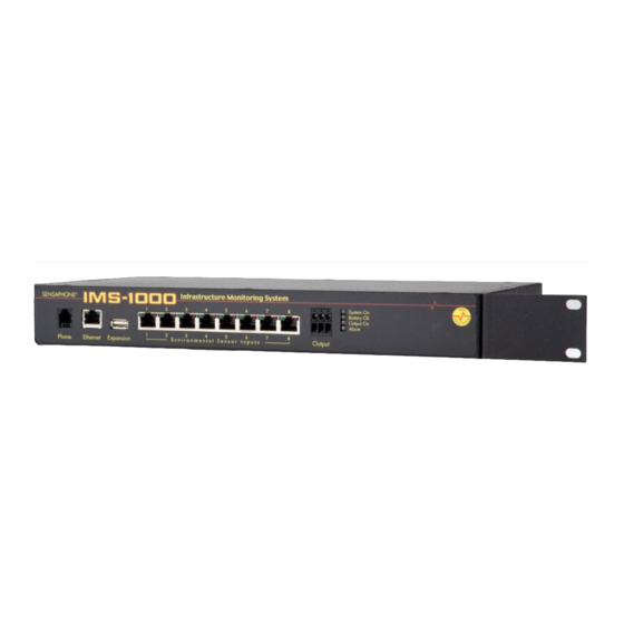
IMS-1000 Manual INSTALLATION and CONFIGURATION Physical Description The IMS-1000 is housed in a 14"w x 1.75"h x 7"d enclosure, which is 1 EIA rack-mount space high. Front Panel Layout The front panel contains connections for eight sensor inputs, Ethernet port, and status LEDs. See... -
Page 21: Sensor Input Leds
Chapter 1: Installation Since the sensor produces an analog signal, it must connect directly to the IMS-1000. The path from the sensor to the IMS unit CANNOT pass through a network Hub or Switch. Sensor Input LEDs Each sensor input has two LEDs (red and green) to indicate the present status of the input. The key below describes the multiple modes of operation. -
Page 22: Alarm Led
IMS-1000 Manual Output LED The Output LED is a visual indication that the Output Relay has been activated. Alarm LED The Alarm LED is a visual indication that a Power, IP Alarm, or Battery Alarm exists. When blinking this LED indicates that the alarm is un–acknowledged, a “steady–on” led indicates that the alarm is acknowledged. -
Page 23: Operating Environment
The IMS-1000 can be installed on a tabletop or shelf. Follow the steps below: 1) Attach the four self-adhesive rubber feet to the four corners on the bottom of the IMS-1000. 2) Place the unit on a tabletop or shelf and connect the power adaptor into a 115VAC outlet. -
Page 24: Connecting Sensors
For example: Suppose you have an IMS-1000 installed in room A and you want to install a sensor in room B. If your existing cabling infrastructure has an unused cable path between room A and room B, then you simply use an RJ-45 interconnect cable to connect the IMS-1000 to the patch panel in room A, and an RJ-45 intercon- nect cable from the wall jack in room B to the sensor. - Page 25 Proceed to the Network Configuration section below. 2) Using a network hub connect only your PC and the IMS-1000 to the hub. Change the IP of your network connection to something in 192.168.1.xxx that is not the same as the default IP of the...
-
Page 26: Parameter Descriptions
IP from the switch’s DHCP server. Log into your switch and see what the IP the switch gave to the IMS-1000. You should now be able to access the following configuration page of the IMS-1000. Point your browser at the following URL where xxx.xxx.xxx.xxx is the IP the switch DHCP server gave your IMS-1000: http://xxx.xxx.xxx.xxx/config.asp... -
Page 27: Battery Maintenance
The IMS-1000 includes an internal UPS that automatically switches to battery backup in the event of an AC power failure. The battery in the IMS-1000 is a 6V 3.4AH sealed lead acid. This battery will keep the unit operating for approximately 3.5 hours when fully charged and under normal oper- ating conditions. -
Page 28: Akkumulator Austauschen
E n v i r o n m e n t a l S e n s o r I n p u t s Figure 6: Battery location Step 1) Locate the power switch on the rear of the unit and turn the IMS-1000 off. Step 2) Disconnect the power cord from the back of the unit. - Page 29 Schritt 10) Den Anschluss mit dem roten Leiter am Pluspol des Akkumulators anschließen. Schritt 11) Den Anschluss mit dem schwarzen Leiter am Minuspol des Akkumulators anschließen. Schritt 12) Die obere Abdeckung des IMS-1000 wieder aufsetzen und mit den Schrauben befestigen. Schritt 13) Das IMS-1000 wieder in das Rack einbauen.
-
Page 30: Ims-1000 Specifications
IMS-1000 Manual IMS-1000 Specifications Operating Specifications Temperature 32–122°F Humidity 5–90% RH non-condensing Power Supply 9VDC / 1 Amp Power Consumption (Type) 10 Watts Power Connection 2.1mm x 10mm jack Dimensions 1.75"h x 7"d x 14"w Weight lbs Backup Battery 6V 3.4AH sealed lead acid Backup Time Up to 3.5 Hours... -
Page 31: Chapter 2: Ims-1000 Programming
Default Login To login for the first time open a web browser and enter the IP address of the IMS-1000 into the address bar and hit enter. The default username is admin and the default password is ims1k. -
Page 32: Network Settings
Remote Web Page The IMS-1000 can send a copy of its web page to another web server via FTP (File Transfer Protocol), so that the web page can be viewed on another network (for example, on the Internet). The unit can create both an html file for normal desktop viewing and also a wml file for viewing with a portable device (cell phone, pocket computer, etc…). -
Page 33: Viewing The Remote Web Page
Viewing the Remote Web Page To view the remote web page that the IMS-1000 uploaded, you need to know its web address. This address corresponds to the Server name, plus the directory, plus the file name of the web page. It will look something like this: http://www.mycompany.com/www/index.html... -
Page 34: Voice Settings
IMS-1000 Manual Enter the telephone number of the IMS-1000 in the Unit Phone Number field. This will appear on alarm messages delivered to numeric pagers and fax machines. Set the Rings Until Answer number. This value determines how many times the line must ring before the IMS-1000 will answer. -
Page 35: Deleting A Profile
The Contacts are the actual telephone numbers, e-mail addresses, pager numbers, etc… that the IMS-1000 will contact when an alarm occurs. You can have up to 4 Contacts per User Profile. Only Contacts which are Enabled when the alarm occurs, will be contacted. E–mail and SNMP contacts will be sent immediately, telephone calls will be dialed in order. -
Page 36: Voice Calls
IMS-1000 uses industry standard TAP protocol, which is supported by most pager systems and cell phone carriers. The IMS-1000 will send the type of alarm, the name of the unit, the Input name, the current value, the programmed high or limit, and the time of the alarm. To program an alphanumer-... -
Page 37: Fax Calls
Once you’ve configured the Input Templates, connect your sensors. This will automatically load the template programming for each sensor. All sensors connect to the IMS-1000 via RJ45 connectors. This allows you to use your existing structured cabling for wiring sensors throughout your infra- structure. -
Page 38: Configuring Environmental Inputs
Data Log Options: The IMS-1000 offers two modes of data logging for each channel. Periodic Data Logging will log the value of the input on a fixed time interval all the time. You can also... -
Page 39: Environmental Input Alarm Logic
The IMS-1000 monitors the presence of all connected sensors to insure the reliability of the sys- tem. When a sensor is unintentionally removed from a IMS-1000 for more than a minute, a trouble alarm is generated and messages will be sent to all contacts. -
Page 40: Special Notes
The IMS-1000 will “test” the programmed IP Address (or Domain Name) on a configurable inter- val. If the address fails to respond the IMS-1000 will go into alarm and notify you of the problem. A more extensive description of the logic is detailed at the end of this section. Note that for voice... - Page 41 “Requires Connect Only”. Alarm Timeout: This is the time allowed for the IP device to respond back to the IMS-1000 when it runs its test. If the device fails to respond in the programmed time then it is considered a fail- ure.
-
Page 42: Alarm Logic
For example: If the ping Retries is set to 3, then the IMS-1000 must fail to ping/connect to the device 4 times in a row (initial attempt + 3 retries) to trip an alarm. If the device were to respond after the second attempt, then the failure counter would reset, thus requiring four subsequent successive failures to trip an alarm. -
Page 43: Removing An Ip Alarm
Chapter 2: Configuration DO NOT set the Alarm Reset Time too short, otherwise you will continue to dispatch the same alarm over and over resulting in numerous phone calls, e-mails, etc. Is IP Alarm Enabled? Change Status to Route Down and wait time between attempts Increment retry count, change status to not... -
Page 44: Configuring A Network Video Camera
IMS-1000. Follow the instructions included with the camera to get it set up on your network. Once the camera is properly set up, go into the IMS-1000 web page and click on Cameras from the main menu. Next, click the Add button at the bottom of the screen. This will bring up the Camera Setup screen (see below). -
Page 45: Voice Recording And Assignment
Custom voice messages can be recorded and assigned to each environmental input and IP alarm. You can also record a message to identify your IMS-1000’s loca- tion. The messages must be recorded by dialing-in to the unit using a touch-tone telephone. When you have finished speaking your message, press any touchtone to stop the recording. - Page 46 Alarm messages into 11-27, and the ID message into 30. Step 2 is to call into the IMS-1000 and record your messages. When the unit answers it will ask for your User Code, then it will speak the menu below. Message recording is prompted with a beep.
-
Page 47: Channel View
The more data being logged, the faster the history log will fill up. The IMS-1000 can store up to 100,000 records. The eventlog contains time-stamped messages that describe activities performed by the unit such as alarm detection, user logins, telephone calls, and alarm acknowledgement. -
Page 48: Viewing History
IMS-1000 Manual Viewing History Datalog and Eventlog history can be viewed by clicking the History button from the main page, then choose the Event log or Data log tab. Use the filters to select which channel to view, the type of records, and the time period - then click the Filter button. -
Page 49: Saving And Loading Programming
Saving and Loading Programming The programming in your IMS-1000 can be saved to a file. This gives you the ability to back up your programming or copy the same programming to another IMS-1000 unit. Note that the file you save will not include parameters from the Network Configuration page. -
Page 50: Configuring The Relay Output
Configuring the Relay Output The IMS-1000 includes a relay output that can be used to control a light, siren, or other low voltage device. The output is a Form-C Normally Open/Normally Closed mechanical relay and is rated for 1A 30VAC or 1A 24VDC. A sample wiring diagram is shown below:... -
Page 51: Modes Of Operation
The output can be programmed to operate in either manual mode or one of two automatic modes (Alarm Condition or Unacknowledged Alarm). The different operating modes are described below: Manual Mode: The output can be operated by using the IMS-1000 Web Page or via touch-tone command during a voice call-in. -
Page 52: Alarm Condition And Unacknowledged Alarm Mode
IMS-1000 Manual Alarm Condition and Unacknowledged Alarm Mode To select one of these modes click the circle labeled Automatic from within the Output Mode sec- tion of the screen. Next, click the circle for either Alarm Condition or Unacknowledged Alarm. -
Page 53: Chapter 3: Operation
This chapter explains how the IMS-1000 operates. Alarm Delivery and Acknowledgment The IMS-1000 will start with the first profile and attempt to send an alarm message to each con- tact. The 1000 will then proceed to the next User Profile. All e–mail, fax, snmp, alphanumeric and numeric pager contacts will be sent the alarm message. -
Page 54: Sample Alarm Messages
Low Humidity ALARM at ABC Federal Savings Bank Humidity - Server Room #2 is now 23.6 %RH Level crossed limit of 25.0 %RH on Monday 7 January 2008, 05:18:00 PM Sample Fax message ***************** IMS-1000 ALARM REPORT ***************** John Smith ABC Widgets Inc. Information Technology FAX NUMBER: 7779992233 FROM: ABC Widgets Inc. -
Page 55: Voice Alarm Dialout
Chapter 3: Operation Voice Status Report and Touch-Tone Commands The IMS-1000 is capable of delivering a spoken status report when called via telephone. The status report can provide information on both environmental conditions and IP alarms. Sample Status Report To receive a status report, call the unit. The unit will answer and begin speaking and request your User Code. -
Page 56: Call-In Alarm Acknowledgment
IMS-1000 Manual “Enter User Code to acknowledge:” {valid User Code is received} “Alarm Acknowledged. ” {main menu} Call-in Alarm Acknowledgment If you receive an alarm message on your pager or in your voice mail, you can still acknowledge the alarm by calling the unit back and entering your User Code. Note that the Intercall Delay must be set to at least 1 minute in order for the unit to answer a call. -
Page 57: Chapter 4: Snmp
Chapter 4: SNMP (Simple Network Management Protocol) The IMS-1000 contains an SNMP agent that supports versions (v1 and V2c), over both UDP and TCP transports. Read and write access to most of the IMS-1000 parameters is provided along with the abil- ity to send traps when alarms occur. - Page 58 Object Identifier (OID), which usually has a name in the form of numbers separated by periods (“.”), like this: .1.3.6.1.x.x.xxxx.x.x.x.x... OIDs for all MIB variables can be determined by browsing the MIB. Below are some examples of the more common OIDs in the IMS-1000: Name: .iso.org.dod.internet.private.enterprises.sensaphone Sensaphone OID: .1.3.6.1.4.1.8338 Environmental Input Values: 1.1.3.1.6.1.1.42 (input number) .0...
-
Page 59: Chapter 5: Ims-1000 Sensors
" hex key Cabling The temperature sensor connects to the IMS-1000 via an RJ-45 cable (e.g. CAT5 cable). The con- nection from the sensor to the IMS-1000 can utilize your existing network wiring infrastructure. For example, the sensor may be installed in another room or another floor. Connect the sensor to your structured wiring network via an RJ-45 jack. -
Page 60: Hidden Cable Surface Installation
IMS-1000 Manual Figure 1: 4810 with Cable exiting through back of enclosure Hidden cable surface installation Bring the RJ-45 cable through the wall at the mounting location. Remove the sensor cover by turn- ing the two hex screws on the bottom of the sensor housing clockwise. Bring the cable through the back of the sensor and hold the sensor housing against the wall. -
Page 61: Configuration
All IMS Solution sensors are auto-configured when you plug them into the IMS-1000. When a new sensor is plugged into the IMS-1000, the configuration is set to the factory default via the Sensor Template. If you have modified these templates, the configuration will be set to the modi- fied configuration. -
Page 62: Sensor Template (Factory Default)
IMS-1000 Manual Sensor Template (factory default) Input Name: Temperature Low Temperature Limit: 50º F High Temperature Limit: 85º F Recognition Time: 60 Seconds Reset Time: 0 Seconds Data Logging: Active Voice: temperature.wav Input Class: Temperature Specifications Range: 5–122 degrees F (-15 to 50 degrees C) Humidity: 5–90 %RH... -
Page 63: Ims-4811 Room Temperature Sensor With Display (Fahrenheit)
" hex key Cabling The temperature sensor connects to the IMS-1000 via an RJ-45 cable (e.g. CAT5 cable). The con- nection from the sensor to the IMS-1000 can utilize your existing network wiring infrastructure. For example, the sensor may be installed in another room or another floor. Connect the sensor to your structured wiring network via an RJ-45 jack. -
Page 64: Hidden Cable Surface Installation
IMS-1000 Manual Figure 1: 4811 with Cable exiting through back of enclosure Hidden cable surface installation Bring the RJ-45 cable through the wall at the mounting location. Remove the sensor cover by turn- ing the two hex screws on the bottom of the sensor housing clockwise. Bring the cable through the back of the sensor and hold the sensor housing against the wall. -
Page 65: Configuration
All IMS Solution sensors are auto-configured when you plug them into the IMS-1000. When a new sensor is plugged into the IMS-1000, the configuration is set to the factory default via the Sensor Template. If you have modified these templates, the configuration will be set to the modi- fied configuration. -
Page 66: Ims-4812 Mini-Temperature Sensor (Fahrenheit)
The Mini-Temperature Sensor comes with an attached 7' cable with an RJ-45 plug on the end. If the sensor is close to the IMS-1000, you can plug the sensor directly to an IMS environmental input. If the cable is too short you can use the included RJ-45 adaptor and a longer patch cable to extend the length. -
Page 67: Sensor Template (Factory Default)
Chapter 5: IMS-1000 Sensors Sensor Template (factory default) Input Name: Temperature Low Temperature Limit: 50º F High Temperature Limit: 85º F Recognition Time: 60 Seconds Reset Time: 0 Seconds Data Logging: Active Voice: temperature.wav Input Class: Temperature Specifications Range: 5–140 degrees F Humidity: 5–90% RH... -
Page 68: Ims-4813 Room Temperature Sensor With Display (Celsius)
" hex key Cabling The IMS-4813 temperature sensor connects to the IMS-1000 via an RJ-45 cable (e.g. CAT5 cable). The connection from the sensor to the IMS-1000 can utilize your existing network wiring infrastruc- ture. For example, the sensor may be installed in another room or another floor. Connect the sensor to your structured wiring network via an RJ-45 jack. -
Page 69: Hidden Cable Surface Installation
Chapter 5: IMS-1000 Sensors Figure 1: 4813 with Cable exiting through back of enclosure Hidden cable surface installation Bring the RJ-45 cable through the wall at the mounting location. Remove the sensor cover by turn- ing the two hex screws on the bottom of the sensor housing clockwise. Bring the cable through the back of the sensor and hold the sensor housing against the wall. -
Page 70: Configuration
All IMS Solution sensors are auto-configured when you plug them into the IMS-1000. When a new sensor is plugged into the IMS-1000, the configuration is set to the factory default via the Sensor Template. If you have modified these templates, the configuration will be set to the modi- fied configuration. -
Page 71: Ims-4814 Ultra Low Temperature Sensor
7' cable with an RJ-45 plug on the end and a weatherproof probe with 12' of cable. If the sensor installation is close to the IMS-1000, you can plug it directly into an IMS environmental input. If the cable is too short you can use the included RJ-45 adaptor and a longer patch cable to extend the length. -
Page 72: Sensor Template
IMS-1000 Manual Caution: Removing a sensor for less than 60 seconds does not produce a trouble alarm. Removing or unplugging a sensor for more than 60 seconds or plugging in a different sensor at any time will cause a trouble alarm. -
Page 73: Ims-4820 Room Humidity Sensor
" hex key Cabling The humidity sensor connects to the IMS-1000 via an RJ-45 cable (e.g. CAT5 cable). The connec- tion from the sensor to the IMS-1000 can utilize your existing network wiring infrastructure. For example, the sensor may be installed in another room or another floor. Connect the sensor to your structured wiring network via an RJ-45 jack. -
Page 74: Hidden Cable Surface Installation
IMS-1000 Manual Figure 1: 4820 with Cable exiting through back of enclosure Hidden cable surface installation Bring the RJ-45 cable through the wall at the mounting location. Remove the sensor cover by turn- ing the two hex screws on the bottom of the sensor housing clockwise. Bring the cable through the back of the sensor and hold the sensor housing against the wall. -
Page 75: Configuration
All IMS Solution sensors are auto-configured when you plug them into the IMS-1000. When a new sensor is plugged into the IMS-1000, the configuration is set to the factory default via the Sensor Template. If you have modified these templates, the configuration will be set to the modi- fied configuration. -
Page 76: Ims-4821 Room Humidity Sensor With Display
(1) 1/16" hex key Cabling The humidity sensor connects to the IMS-1000 via an RJ-45 cable (e.g. CAT5 cable). The connec- tion from the sensor to the IMS-1000 can utilize your existing network wiring infrastructure. For example, the sensor may be installed in another room or another floor. Connect the sensor to your structured wiring network via an RJ-45 jack. -
Page 77: Hidden Cable Surface Installation
Chapter 5: IMS-1000 Sensors Figure 1: 4821 with Cable exiting through back of enclosure Hidden cable surface installation Bring the RJ-45 cable through the wall at the mounting location. Remove the sensor cover by turn- ing the two hex screws on the bottom of the sensor housing clockwise. Bring the cable through the back of the sensor and hold the sensor housing against the wall. -
Page 78: Configuration
All IMS Solution sensors are auto-configured when you plug them into the IMS-1000. When a new sensor is plugged into the IMS-1000, the configuration is set to the factory default via the Sensor Template. If you have modified these templates, the configuration will be set to the modi- fied configuration. -
Page 79: Ims-4830 Water Detection Sensor
(4) Rubber feet Cabling The water detection sensor connects to the IMS-1000 via an RJ-45 cable (e.g. CAT5 cable). The connection from the sensor to the IMS-1000 can utilize your existing network wiring infrastruc- ture. For example, the sensor may be installed in another room or another floor. Connect the sensor to your structured wiring network via an RJ-45 jack. -
Page 80: Mounting
All IMS Solution sensors are auto-configured when you plug them into the IMS-1000. When a new sensor is plugged into the IMS-1000, the configuration is set to the factory default via the Sensor Template. If you have modified these templates, the configuration will be set to the modi- fied configuration. -
Page 81: Sensor Template (Factory Default)
Chapter 5: IMS-1000 Sensors Caution: Removing a sensor for less than 60 seconds does not produce a trouble alarm. Removing or unplugging a sensor for more than 60 seconds or plugging in a different sensor at any time will cause a trouble alarm. -
Page 82: Ims-4840 External Power Sensor
(4) Rubber feet Cabling The Power Sensor connects to the IMS-1000 via an RJ-45 cable (e.g. CAT5 cable). The connec- tion from the sensor to the IMS-1000 can utilize your existing network wiring infrastructure. For example, the sensor may be installed in another room or another floor. Connect the sensor to your structured wiring network via an RJ-45 jack. -
Page 83: Mounting
Chapter 5: IMS-1000 Sensors Figure 1: Connections to the IMS-4840 Mounting The sensor can be mounted to a wall or lie flat on the floor. To mount the sensor to a wall, install the two drywall anchors (if necessary) and attach the Power Sensor using the two #6 tapping screws. -
Page 84: Configuration
All IMS Solution sensors are auto-configured when you plug them into the IMS-1000. When a new sensor is plugged into the IMS-1000, the configuration is set to the factory default via the Sensor Template. If you have modified these templates, the configuration will be set to the modi- fied configuration. -
Page 85: Ims-4841 15A High Current Sensor
IEC320 C14 inlet and C13 outlet connectors. Cabling The Current Sensor connects to the IMS-1000 via an RJ-45 cable (e.g. CAT5 cable). The connec- tion from the sensor to the IMS-1000 can utilize your existing network wiring infrastructure. For example, the sensor may be installed in another room or another floor. -
Page 86: Mounting
Figure 2: Mounting the sensor Configuration All IMS Solution sensors are auto-configured when you plug them into the IMS-1000. The 15A Current Sensor will identify itself as a 4-20mA transducer. On the Properties screen for this sensor you must select the sensor type: Current Sensor. When a sensor is removed, or the connection is disrupted, the configuration data remains intact but the sensor will go into trouble status and gener- ate a trouble alarm. - Page 87 Chapter 5: IMS-1000 Sensors Sensor Template (factory default) Input Name: Transducer High Limit: 100 Low Limit: 0 Recognition Time: 60 Seconds Reset Time: 0 Seconds Data Logging: Active Voice: none Input Class: Other Specifications Range: 0–15 Amps (0-250 VAC, 50/60 Hz) Operating Temperature: 5-104°F (-15 to 40°C)
-
Page 88: Ims-4842 20A High Current Sensor
IEC320 C20 inlet and C19 outlet connectors. Cabling The Current Sensor connects to the IMS-1000 via an RJ-45 cable (e.g. CAT5 cable). The connection from the sensor to the IMS-1000 can utilize your existing network wiring infra¬structure. For example, the sensor may be installed in another room or another floor. -
Page 89: Configuration
Figure 2: Mounting the sensor Configuration All IMS Solution sensors are auto-configured when you plug them into the IMS-1000. The 20A Current Sensor will identify itself as a 4-20mA transducer. On the Properties screen for this sensor you must select the sensor type: Current Sensor. When a sensor is removed, or the connection is disrupted, the configuration data remains intact but the sensor will go into trouble status and gener- ate a trouble alarm. -
Page 90: Ims-4850 Dry Contact Bridge
Figure 1: Connections to the IMS-4850 Cabling The Dry Contact Bridge connects to the IMS-1000 via an RJ-45 cable (e.g. CAT5 cable). The connection from the sensor to the IMS-1000 can utilize your existing network wiring infrastructure. For example, the sensor may be installed in another room or another floor. Connect the bridge to your structured wiring network via an RJ-45 jack. -
Page 91: Mounting
All IMS Solution sensors are auto-configured when you plug them into the IMS-1000. When a new sensor is plugged into the IMS-1000, the configuration is set to the factory default via the Sensor Template. If you have modified these templates, the configuration will be set to the modi- fied configuration. -
Page 92: Sensor Template (Factory Default)
IMS-1000 Manual Sensor Template (factory default) Input Name: Contact Bridge Recognition Time: 3 Seconds Reset Time: 0 Seconds Data Logging: Active Voice: dry contact.wav Input Class: Other Specifications Input: Normally Open or Normally Closed dry contact Source/Sense Voltage: 14VDC Source/Sense Current:... -
Page 93: Ims-4851 4-20Ma Bridge
Figure 1: 4–20mA transducer wiring to IMS-4851 Terminal Block Cabling The 4-20mA Bridge connects to the IMS-1000 via an RJ-45 cable (e.g. CAT5 cable). The connec- tion from the sensor to the IMS-1000 can utilize your existing network wiring infrastructure. For example, the bridge may be installed in another room or another floor. -
Page 94: Mounting
IMS-1000. When a new sensor is plugged into the IMS-1000, the configuration is set to the factory default via the Sensor Template. If you have mod- ified these templates, the configuration will be set to the modified configuration. When a sensor is removed, or the connection is disrupted, the configuration data remains intact but the sensor will go into trouble status and generate a trouble alarm. -
Page 95: Sensor Template (Factory Default)
Chapter 5: IMS-1000 Sensors Caution: Removing a sensor for less than 60 seconds does not produce a trouble alarm. Removing or unplugging a sensor for more than 60 seconds or plugging in a different sensor at any time will cause a trouble alarm. -
Page 96: Ims-4860 Door Switch
The bridge may be mounted either on a wall or rest on the floor. The switch is mounted to doors or windows you wish to monitor. The electrical connec- tion between the bridge and IMS-1000 is made via RJ-45 patch cable. Package Contents... -
Page 97: Configuration
The choice depends on your specific application. Cabling The Door Switch connects to the IMS-1000 via an RJ-45 cable (e.g. CAT5 cable) from the bridge. The connection from the bridge to IMS-1000 can utilize your existing network wiring infrastruc- ture. -
Page 98: Specifications
IMS-1000 Manual Sensor Template (factory default) Input Name: Contact Bridge Recognition Time: 3 Seconds Reset Time: 0 Seconds Data Logging: Active Voice: dry contact.wav Input Class: Other Specifications Bridge: Input: Normally Open or Normally Closed dry contact Source/Sense Voltage: 14VDC... -
Page 99: Ims-4861 Passive Infrared Detection Sensor
The Passive Infrared Detection Sensor comes with an attached 7' cable with an RJ-45 plug on the end. If the sensor is close to the IMS-1000, you can plug the sensor directly to an IMS environ- mental input. If the cable is too short you can use the included RJ-45 adaptor and a longer patch cable to extend the length. -
Page 100: Configuration
All IMS Solution sensors are auto-configured when you plug them into the IMS-1000. When a new sensor is plugged into the IMS-1000, the configuration is set to the factory default via the Sensor Template. If you have modified these templates, the configuration will be set to the modi- fied configuration. -
Page 101: Sensor Template (Factory Default)
Chapter 5: IMS-1000 Sensors PULSE/AUTO: Pulse Count Jumper Jumper in position 1 (to the right): Jumper setting for a stable environment without air drafts. Jumper in position AUTO (to the left): Setting for a harsh environment. Figure 2: Sensitivity adjustment and jumper locations... -
Page 102: Ims-4862 Smoke Detector Sensor
The Smoke Detector Sensor comes with an attached 7' cable with an RJ-45 plug on the end. If the sensor is close to the IMS-1000, you can plug the sensor directly to an IMS environmental input. If the cable is too short you can use the included RJ-45 adaptor and a longer patch cable to extend the length. -
Page 103: Sensor Template (Factory Default)
Chapter 5: IMS-1000 Sensors Sensor Template (factory default) Input Name: Smoke Detector Recognition Time: 10 Seconds Reset Time: 0 Seconds Data Logging: Active Voice: smoke detector.wav Input Class: Smoke Specifications Sensitivity: 2.0 ± .37% - .39% /ft. Contact Rating: 2 AMP 28 VDC or 120 VAC resistive Heat sensor rating: Fixed 135º... -
Page 104: Technical Support For The Ims-1000 Sensors
IMS-1000 Manual Technical Support for the IMS-1000 Sensors For questions about installing any of these sensors, please contact your local IMS Solution Reseller or VAR or contact the manufacturer directly at: Phonetics, Inc. Tel: 610.558.2700 901 Tryens Road Fax: 610.558.0222 Aston, PA 19014 Email: sensaphone.com... -
Page 105: Appendix A: Weekly Testing Procedure
We recommend that you test your IMS-1000 system weekly to be sure it is functioning properly. This will ensure that when a problem arises the IMS-1000 will be ready to alert the appropriate personnel. A test log template is included at the back of this manual. -
Page 106: Appendix B: Troubleshooting
Yes. Why won’t my IMS-1000 dial out? n Check that you have a Touch-Tone telephone line. The IMS-1000 will not be able to dial out if it’s on a Pulse telephone line or a digital extension from a telephone system. -
Page 107: Appendix C: Ims-1000 Accessories
IMS-1000 Power Sensor IMS-4841 IMS-1000 15A Current Sensor IMS-4842 IMS-1000 20A Current Sensor IMS-4850 IMS-1000 Dry Contact Bridge IMS-4851 IMS-1000 4–20mA Bridge IMS-4860 IMS-1000 Door Switch IMS-4861 IMS-1000 Passive Infrared Motion Detector w/7' RJ-45 Cable IMS-4862 IMS-1000 Smoke Detector w/7' RJ-45 Cable... -
Page 108: Appendix D: Returning An Ims Unit For Repair
IMS-1000 Manual Appendix D: Returning an IMS Unit for Repair In the event that any of your Sensaphone IMS-1000 units does not function properly, we suggest that you do the following: 1) Record your observations regarding the individual unit’s malfunction. -
Page 109: Test Log
Test Log... -
Page 111: Index
Index Programming Alarm Parameters 39–40 Removing 43 Accessories 104 Alarm Delivery & Acknowledgment 50–52 Acknowledgment 50 Quick Start Guide Sample Alarm Messages 51–53 Configure the Unit Properties 31 Environmental Input Alarm Logic 38–39 Default Username and Password 31 Message Pop-Ups 48–49 Response Camera Snapshots on Alarm 44–45 Trouble Alarms 39... - Page 112 IMS-1000 Manual Specifications & Defaults 81–101, 84–101, 86–101 Sample Status Report 52 IMS-4850 Dry Contact Bridge 82–84 Voice Alarm Dialout 52–53 Cabling 87–88 Configuration 88 Mounting 88 Warranty ix–x Specifications & Defaults 89–101 Web Page Wiring the Contact 87 Updating 47...
Need help?
Do you have a question about the IMS-1000 and is the answer not in the manual?
Questions and answers