Table of Contents
Advertisement
Quick Links
PROPER USE GUIDELINES
Cumulative Trauma Disorders can result from the prolonged use of manually powered hand tools. Hand tools are intended for occasional use
and low volume applications. A wide selection of powered application equipment for extended-use, production operations is available.
Indenter
Crimping Die
Assembly
220196-1
1. INTRODUCTION
This tool is designed primarily for field installation,
NOTE
repair, maintenance work, or prototyping in
i
industrial, commercial, or institutional applications.
Tyco Electronics offers a variety of tools to satisfy
your performance requirements. For additional
information, contact the Tooling Assistance Center
at 1-800-722-1111.
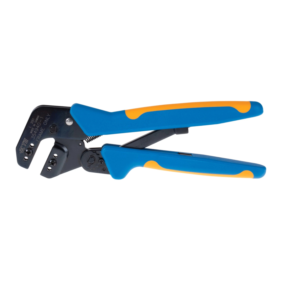
This instruction sheet covers the use and maintenance
of PRO-CRIMPER III Assembly 58506-3, which
includes PRO-CRIMPER III Frame Assembly 354940-
1 and Crimping Die Assembly 220196-1. The die
assembly crimps AMP Miniature UHF Series Plug,
Jack, and Bulkhead Jack connectors onto coaxial
cable.
Dimensions in this instruction sheet are in metric
NOTE
units [with U.S. customary units in brackets].
Figures are not drawn to scale.
i
Reasons for reissue of this document are provided in
Section 7, REVISION SUMMARY.
©2011 Tyco Electronics Corporation, Berwyn, PA
All Rights Reserved
TE logo and Tyco Electronics are trademarks.
*Trademark. Other products, logos, and company names might be trademarks of their respective owners.
PRO-CRIMPER* III Assembly 58506-3
and Die Assembly 220196-1
Anvil
Figure 1
2. DESCRIPTION
Die Assembly 220196-1 consists of an indenter die
and an anvil die, which when closed form two crimping
chambers. The larger chamber crimps the ferrule of
the connector onto the coaxial cable, and the smaller
chamber crimps the center contact onto the center
conductor of the cable. Each die is held in Frame
Assembly 354940-1 by a single screw.
3. DIE INSTALLATION
TOOLING ASSISTANCE CENTER 1-800-722-1111
PRODUCT INFORMATION 1-800-522-6752
1. Close the tool handles until the ratchet releases,
then allow the handles to open fully.
2. Insert each die into the tool jaws and align
retaining hole in each die with the associated hole in
the tool frame.
3. Thread retaining screws into the holes, but do not
tighten the screws.
4. Begin to close the tool handles, making sure that
the dies align properly.
This controlled document is subject to change.
For latest revision and Regional Customer Service,
visit our website at www.tycoelectronics.com
Instruction Sheet
408-2835
01 MAR 11 Rev F
PRO-CRIMPER III
Frame Assembly
354940-1
1 of 6
LOC B
Advertisement
Table of Contents

Related Manuals for Tyco Electronics PRO-CRIMPER III


Summary of Contents for Tyco Electronics PRO-CRIMPER III
- Page 1 The larger chamber crimps the ferrule of Tyco Electronics offers a variety of tools to satisfy the connector onto the coaxial cable, and the smaller your performance requirements. For additional...
- Page 2 408-2835 Once the anvil has entered the indenter, place a This tool will not provide a crimp conforming to NOTE NOTE copper bus bar (1.57 mm ±.050 mm [.062 in. ±.002 military requirements. in.] diameter) into the center contact section of the die assembly.
- Page 3 408-2835 Flared Braid Ferrule Connector Body Collar Cable Inserted Into Connector Body Collar Slipped Forward Over Connector Body Push Ferrule Forward Crimp Center Protruding Center Over Braid. Flange Contact After Conductor Butts Against Connector Inserting Cable Body. Crimp Ferrule to Complete Crimp.
- Page 4 408-2835 Crimp Location B Crimp Location Plug Locator Detents Plug Connector Butts Crimp Location A Collar Against Locator Ferrule Insert Center Contact Through Locator with Crimping Die Connector Body Positioned as Shown Figure 4 3. Insert stripped cable into the center contact of the jack until cable dielectric butts against the contact.
- Page 5 408-2835 Crimp Wire Barrel Portion of Jack Assembly Procedure Center Contact Ferrule Push Ferrule Forward Over Jack Braid. Flange Butts Against Crimped Center Connector Body. Crimp Body Contact Inserted Ferrule in Hand Tool to into Connector Complete Crimp. Center Contact Figure 6 5.
- Page 6 6. REPLACEMENT chipped, worn, or cracked areas. If damage is evident, the dies must be replaced. Refer to Section Order replacements through your Tyco Electronics Representative, or call 1-800-526-5142, or send a 6, REPLACEMENT. facsimile of your purchase order to 1-717-986-7605, or 5.3.
Need help?
Do you have a question about the PRO-CRIMPER III and is the answer not in the manual?
Questions and answers