
Related Manuals for Time Electronics 9814


Summary of Contents for Time Electronics 9814
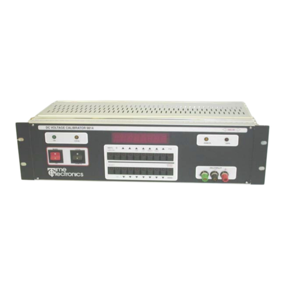
- Page 1 9814 Programmable D.C. Voltage Calibrator Technical Manual Time Electronics Ltd Unit 11 Botany Industrial Estate Tonbridge, Kent, TN9 1RH Tel: 01732 355993 Fax: 01732 770312 E-Mail: mail@TimeElectronics.co.uk Web Site: www.TimeElectronics.co.uk V3 10/07/03...
-
Page 2: Table Of Contents
Technical Description ............... 22 Calibration.................. 24 Spare Parts ................26 10) Guarantee and Servicing ............27 All Time Electronics' instruments are subject to continuous development and improvement and in consequence may incorporate minor detail changes from the information contained herein. -
Page 3: Introduction
Reference amplifier etc. are located on a separate plug in Euro board. All boards are easily accessible form the rear of the instrument. The 9814 can if required be operated in a manual mode with all controls lo- cated on the front panel. -
Page 4: Specifications
Page 4 Section 2 - Specifications Output: 0 to 10V in 4 ranges D.C. Accuracy: 10V & 1V Ranges: 0.01% of setting, +/- 0.001% of range, +/-3uV 100mV & 10mV ranges: 0.02% of setting, +/- 0.005% of range, +/-2uV. Output resistance: 10 mohms on 10V &... -
Page 5: Front Panel Controls
Page 5 Section 3 - Front Panel Controls 2 LEDS - A) ON Illuminates when unit is on B) LOCAL Illuminates when unit is in LOCAL mode 2 PRESS SWITCHES - A) MAINS / ON B) LOCAL / REMOTE 20 PRESS SWITCHES - Select range, output level and polarity 20 LED STATUS - Indicates range and operating mode. -
Page 6: Local Operation
Section 4 - Local Operation Mains Voltage Selection Situated at the rear of the 9814 on the power module, are the mains inlet socket, two fuses and the voltage selector. The mains voltage is displayed in a small window. Ac- cess to the fuses and mains selector is via a lever down flap. - Page 7 2, 4, 6, 7 and 8 reading left to right. Only digits 6 and 8 are used on the 9814. The mode is incremented using the arrowed key beneath the function digit. The following paragraphs correspond to digit numbers and explain each of the functions and associated modes.
- Page 8 NOTE Output errors are not detected on the 10mV and 100mV ranges. The user can select one of 4 ways in which the 9814 will respond to an output error de- tailed below. Mode 1. The output will be set to zero immediately and ‘OP ERROR’ displayed. To continue using the 9814, the fault must be rectified and the output re-selected.
- Page 9 NOTE: Running self test with the calibration key plugged in will result in the loss of cali- bration data. To exit from self test mode, turn the 9814 off, set the unit address on the IEEE switches and switch on again.
-
Page 10: Remote Operation
Introduction The IEEE-488 interface sometimes called GPIB (General Purpose Interface Bus) or HPIB (Hewlett Packard Interface Bus) allows remote control of the 9814 by a suitable computer. Repetitive calibration work can be speedily and accurately carried out giving printed results if required. - Page 11 Page 11 IEC Bus Connections A user requiring to connect the 9814 to a European standard bus (IEC), must be aware of the differences in connector pin assignments from the IEEE bus and provide a suitable interface. Table 5.1 compares the pin designations for each standard.
- Page 12 GND 11 IEEE Address selection Before operating the 9814 over the IEEE, set the address on the rear of the unit to the required address and operating mode. Addresses 0 and 16 are reserved for recalibration in AUTO-CAL mode and should not be used unless recalibrating the instrument.
- Page 13 Switch 6 - IEEE talk (transmit) mode. Switch 7 - IEEE listen (receive) mode. Switch 8 - Dual Primary Addressing mode In this mode, the 9814 will respond to two primary addresses differing only in the least significant bit. For example, if the unit ad- dress selection switches are set for an address of 8, the unit will also respond to ad- dress 9.
- Page 14 IEEE command format IEEE commands are comprised of characters from the ASCII set. A series of commands can be used to simulate the manual operation of the 9814. The commands must be in one of the following formats: A single uppercase character (A to Z).
- Page 15 Invalid terminating characters cause the IEEE bus to hang. The terminator is controller dependent and the 9814 allows either CR or LF to be used, as determined by the 9814 Command T1 or T2. Note that the T1 or T2 command (terminating setting) must be done before the ‘D’...
- Page 16 Letter and number command E1 to E4 output error mode Selects one of 4 possible error modes which determine the action taken by the 9814 on detection of an output error. E1: (default). Display OP ERROR and turns off output immediately on detection of an out- put error, remains in this condition until reset by another command.
- Page 17 TRIGGER 708 !EXECUTE COMMAND TO EXIT GET MODE K1/K2 enable/disable front panel control K1 - Set the 9814 to respond to front panel control K2 - Disables front panel controls P (n) set percentage deviation Set deviation on present output in range +9.999 and –9.999.
- Page 18 Page 18 T1 (default) : carriage return T2 : line feed. Setting an output value Transmit the voltage or current required as an ASCII string. EXAMPLES (HP BASIC) on the 1 volt range (R3) OUTPUT 708;2-0.3765” !SET OUTPUT TO –0.3765 VOLTS OUTPUT 708;”1.9”...
-
Page 19: Fault Diagnosis
Fault check list If the 9814 is completely dead with no front panel lights, check the following: Mains supply. Mains fuse blown in plug. - Page 20 Main Frame The 9814 is constructed on a 19 inch Euro-card frame. Cards and modules plug into the frame from the rear of the unit. All modules and printed circuit boards connect to the 64-way data bus via a DIN 41612 type connector.
- Page 21 Page 21 Disconnect the multipin plug that connects the rear panel to the IEEE panel. Before the boards can be removed, the black retaining clips located at the bottom of the frame must be depressed. NOTE: The IEEE multipin connector is NOT polarized and can be accidentally reversed during replacement.
-
Page 22: Technical Description
Page 22 Section 7 - Technical Description Introduction This section contains a brief technical description of the 9814, starting with the main- frame and associated modules, followed by the plug-in boards. The technical description is divided into the following parts:... - Page 23 32 lines of parallel input/output (I/O). The microprocessor used in the 9814 is the Motorola MC 6802. A 3.2768MHz crystal, divided down internally by the 6802, supplies the 8192 kHz clock. Parallel I/O lines is provided with a pull-up resistor.
-
Page 24: Calibration
IEEE address switches to the left and switch on). Self test can be run without insert- ing the CAL key which leaves the calibration factors unchanged. If the CAL key is inserted when the 9814 is not addressed for auto-cal, the display will flash ERROR 7. - Page 25 Notes: Addresses 0 and 16 only should be used for calibration. If the 9814 is operated in auto-cal mode with the CAL key not inserted, the deviation and offset functions will not work. The IEEE address is only read when the 9814 is first switched on.
-
Page 26: Spare Parts
Page 26 Section 9 - Spare Parts ITEM ORDER CODE 12v Relay 6314 Key Switch 6362 8 way D.I.L. switch 6306 D/A module 9516 Reference module 9599 IEEE connector 6420 Mains fuse 20mm (1A) 6110 Fuse 20mm (2A) 6111 IEEE driver (3448) 4555 IEEE interface (68488) 4556... -
Page 27: Guarantee And Servicing
Section 10 - Guarantee and Servicing Guarantee Period The 9814 is guaranteed against defects in materials and workmanship for a period of one year from its delivery to the customer. We maintain comprehensive after sales Facilities and the unit can, if necessary be re- turned to us for servicing.
Need help?
Do you have a question about the 9814 and is the answer not in the manual?
Questions and answers