CORNING EDGE8 Manual
Hide thumbs
Also See for EDGE8:
- Quick start manual (25 pages) ,
- Manual (11 pages) ,
- Installation (4 pages)
Table of Contents
Advertisement
Quick Links
EDGE8™ Solution
P/ N 003-1002-BEN
Issue 4
related literature |
003-997-QSG-AEN
003-998-QSG-AEN
003-1000-QSG-AEN
003-1001-QSG-AEN
006-407-AEN
006-407-QSG-AEN
Table of Cont ent s
1.
General . . . . . . . . . . . . . . . . . . . . . . . . . . . . . . . . . . . . . . . . . . . . . . . . . . . . . . . . . . . . . . . . . . . . . . . . . . . . . . . . . . . . . . . . . . . . . . . . . . 2
2.
Carton Contents . . . . . . . . . . . . . . . . . . . . . . . . . . . . . . . . . . . . . . . . . . . . . . . . . . . . . . . . . . . . . . . . . . . . . . . . . . . . . . . . . . . . . . . . . . 2
3.
Tools and Materials Required . . . . . . . . . . . . . . . . . . . . . . . . . . . . . . . . . . . . . . . . . . . . . . . . . . . . . . . . . . . . . . . . . . . . . . . . . . . . . . 2
3.1
Tools . . . . . . . . . . . . . . . . . . . . . . . . . . . . . . . . . . . . . . . . . . . . . . . . . . . . . . . . . . . . . . . . . . . . . . . . . . . . . . . . . . . . . . . . . . . . . . 2
3.2
Materials . . . . . . . . . . . . . . . . . . . . . . . . . . . . . . . . . . . . . . . . . . . . . . . . . . . . . . . . . . . . . . . . . . . . . . . . . . . . . . . . . . . . . . . . . . 2
4.
Installation . . . . . . . . . . . . . . . . . . . . . . . . . . . . . . . . . . . . . . . . . . . . . . . . . . . . . . . . . . . . . . . . . . . . . . . . . . . . . . . . . . . . . . . . . . . . . . 3
4.1
Rack or Frame Mounting . . . . . . . . . . . . . . . . . . . . . . . . . . . . . . . . . . . . . . . . . . . . . . . . . . . . . . . . . . . . . . . . . . . . . . . . . . . . 3
4.2
Install Trunk Cables . . . . . . . . . . . . . . . . . . . . . . . . . . . . . . . . . . . . . . . . . . . . . . . . . . . . . . . . . . . . . . . . . . . . . . . . . . . . . . . . . 3
4.2.1
Trunk Cable Placement w ith the Pulling Grip . . . . . . . . . . . . . . . . . . . . . . . . . . . . . . . . . . . . . . . . . . . . . . . . . . . . . 5
4.2.2
Pulling Grip Removal . . . . . . . . . . . . . . . . . . . . . . . . . . . . . . . . . . . . . . . . . . . . . . . . . . . . . . . . . . . . . . . . . . . . . . . . . . . . .6
4.3
(OPTIONAL) Install CDF Bracket . . . . . . . . . . . . . . . . . . . . . . . . . . . . . . . . . . . . . . . . . . . . . . . . . . . . . . . . . . . . . . . . . . . . . . . 7
4.4
Install Trunk Cables from Either Side of the Housing . . . . . . . . . . . . . . . . . . . . . . . . . . . . . . . . . . . . . . . . . . . . . . . . . . . 8
4.4.1
Inst alling Trunk Cable Using Keyhole Cradle . . . . . . . . . . . . . . . . . . . . . . . . . . . . . . . . . . . . . . . . . . . . . . . . . . . . . .9
4.4.2
Inst alling Trunk Cable Using U-Clip Cradle . . . . . . . . . . . . . . . . . . . . . . . . . . . . . . . . . . . . . . . . . . . . . . . . . . . . . . .10
4.4.3
Inst alling Trunk Cable wit h Keyhole Adapt er . . . . . . . . . . . . . . . . . . . . . . . . . . . . . . . . . . . . . . . . . . . . . . . . . . . . .10
4.5
Install Trunk Cables from Rear of Housing . . . . . . . . . . . . . . . . . . . . . . . . . . . . . . . . . . . . . . . . . . . . . . . . . . . . . . . . . . . . 11
4.6
(OPTIONAL) Remove Housing Trunk Plate . . . . . . . . . . . . . . . . . . . . . . . . . . . . . . . . . . . . . . . . . . . . . . . . . . . . . . . . . . . . 12
4.7
Install EDGE8™ Standard Modules . . . . . . . . . . . . . . . . . . . . . . . . . . . . . . . . . . . . . . . . . . . . . . . . . . . . . . . . . . . . . . . . . . . 13
4.7.1
Into EDGE8-01 U-SP , EDGE8-02U, and EDGE8-04U Housings. . . . . . . . . . . . . . . . . . . . . . . . . . . . . . . . . . . . . . 1 3
4.7.2
Into EDGE8-01 U Housing . . . . . . . . . . . . . . . . . . . . . . . . . . . . . . . . . . . . . . . . . . . . . . . . . . . . . . . . . . . . . . . . . . . . . . . . 14
4.8
Install EDGE8™ Port Breakout Modules . . . . . . . . . . . . . . . . . . . . . . . . . . . . . . . . . . . . . . . . . . . . . . . . . . . . . . . . . . . . . . 15
4.8.1
Into EDGE8-01 U-SP , EDGE8-02U, and EDGE8-04U Housings. . . . . . . . . . . . . . . . . . . . . . . . . . . . . . . . . . . . . . 15
4.8.2
Into EDGE8-01 U Housing . . . . . . . . . . . . . . . . . . . . . . . . . . . . . . . . . . . . . . . . . . . . . . . . . . . . . . . . . . . . . . . . . . . . . . . .16
4.9
Connect Jumpers to EDGE8™ Modules . . . . . . . . . . . . . . . . . . . . . . . . . . . . . . . . . . . . . . . . . . . . . . . . . . . . . . . . . . . . . . 16
4.10
4.10.1
Init ial MTP Adapter Panel Installation . . . . . . . . . . . . . . . . . . . . . . . . . . . . . . . . . . . . . . . . . . . . . . . . . . . . . . . . . . . 17
4.10.2
5.
Recordkeeping . . . . . . . . . . . . . . . . . . . . . . . . . . . . . . . . . . . . . . . . . . . . . . . . . . . . . . . . . . . . . . . . . . . . . . . . . . . . . . . . . . . . . . . . . . 19
5.1
Hardware Labelling . . . . . . . . . . . . . . . . . . . . . . . . . . . . . . . . . . . . . . . . . . . . . . . . . . . . . . . . . . . . . . . . . . . . . . . . . . . . . . . . 19
5.2
Cable/ Jumper Labelling . . . . . . . . . . . . . . . . . . . . . . . . . . . . . . . . . . . . . . . . . . . . . . . . . . . . . . . . . . . . . . . . . . . . . . . . . . . . 23
Instruction, EDGE8-01 U Quick Start Guide
Instruction, EDGE8-01 U-SP Quick Start Guide
Instruction, EDGE8-02U Quick St art Guide
Instruction, EDGE8-04U Quick Start Guide
Instruction, Field Tool for MTP® PRO Connectors Installat ion
Instruction, Field Tool for MTP® PRO Connectors Quick Start Guide
®
Adapter Panels . . . . . . . . . . . . . . . . . . . . . . . . . . . . . . . . . . . . . . . . . . . . . . . . . . . . . . . . . . . . . . . . . . . . . . . . . 17
®
Jumper, Harness, or Extender Trunk to Front of MTP Adapter Panels . . . . . . . . . . . 18
Standard Recom m ended Procedure 003-1002-BEN | Issue 4 | January 2019 | Page 1 of 26
Advertisement
Table of Contents

Subscribe to Our Youtube Channel
Related Manuals for CORNING EDGE8


Summary of Contents for CORNING EDGE8
-
Page 1: Table Of Contents
Into EDGE8-01 U-SP , EDGE8-02U, and EDGE8-04U Housings........ -
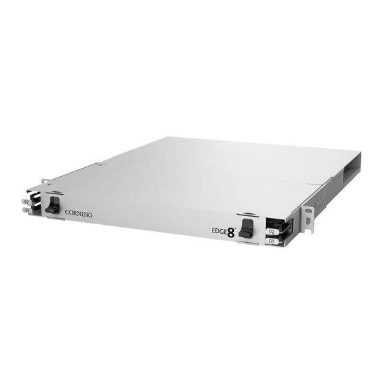
Page 2: General
Figure 1 — EDGE8™ Housings This document describes inst allation of the EDGE8™ 1U, 1U-SP , 2U, and 4U Housing Solut ions (Figure 1). Except w here inst allation of another housing is unique, only the 4U housing is illust rat ed. -
Page 3: Installation
Install Trunk Cables The EDGE8™ trunk cable is supplied w ith factory-installed protection/ pulling grips (Figure 3) to protect the connectors and their bres by coupling the pulling load back to the cable. The cradle is used to install the furcation plug into the housing. - Page 4 Weather Precautions • Always follow the recommended storage temperature guidelines for the cable when storing a trunk/pigtail. Each cable type will have a storage temperature rating that can be found on the product speci cation sheets. Storage outside of these ranges can cause damage to the cables.
-
Page 5: Trunk Cable Placement W Ith The Pulling Grip
CAUTION: This preconnectorised pulling grip has a maximum tensile rating of 100 pounds (44.5 kg). NEVER EXCEED THIS TENSION DURING INS TALLATION. The pulling grip has a m inim um bend radius of 18 inches (45.72 cm). Refer to the EDGE8™ speci cation sheet for cable/grip dimensions and appropriate duct sizes. -
Page 6: Pulling Grip Removal
4.2.2 Pulling Grip Removal Step 1: Remove the pull line and clean any dirt or debris from the outer surfaces of the sleeve. Disassemble the pulling sleeve on a work surface free from dirt, excessive heat , or any solvents. IM PORTANT: Step 2: Lift the hook-and-loop aps to expose... -
Page 7: Optional) Install Cdf Bracket
Step 6: Use the tabs on the furcation end of the coupler to separat e the coupler’s tw o halves. Step 7: Remove the coupler halves from the trunk furcation body and dispose of t he coupler assembly (Figure 9). 96- and 144- bre Trunks: Step 8: Starting w ith the mesh bag closest to the furcation body,... -
Page 8: Install Trunk Cables From Either Side Of The Housing
Insert furcation plug into cradle as seen in Figure 12 or Figure 1 3 and mount cradle onto CDF bracket Step 3: (Figure 11). ® Then route trunks inside the housing through the brushed cable entry slots.Term inat e the MTP Step 4: connector at the back of the LC module or MTP adapter panel. -
Page 9: Inst Alling Trunk Cable Using Keyhole Cradle
4.4.1 Inst alling Trunk Cable Using Keyhole Cradle Step 1: Remove the access or rear cover from the housing to reach the backplat e (Figure 1). Step 2: Open cradle provided inside the reel and press each t runk cable furcation plug into cradle (Figure 1 2 - double-stack cradle or Figure 13 - single-stack cradle). -
Page 10: Install Trunk Cables From Rear Of Housing
Figure 14 – Install Trunk Cable w ith Keyhole Adapter Inst all Trunk Cables from Rear of Housing If rear cable entry into the housing is desired or necessary, the backplates must be turned 180 degrees before installing the cables. Remove existing backplates by removing the four screws (Figure 15). -
Page 11: Optional) Remove Housing Trunk Plate
(OPTIONAL) Remove Housing Trunk Plat e If cable entry st rain-relief is accomplished in a location ext ernal to the housing, the trunk plate may be removed to allow more room behind the housing (Figure 16). Step 1: (For 4U housing only) Remove side panel from each side of the housing. Step 2: Remove any screw s holding the access panels to the housing. -
Page 12: Install Edge8™ Standard Modules
Loosely capture bre slack with hook-and-loop st raps, if desired (Figure 17). Step 6: Figure 17 — Inst all EDGE8™ St andard Modules CAUTION: When removing the trays, position yourself in the center of the rack and use both hands to pull the tray out . -
Page 13: Into Edge8-01U Housing
4.7.2 Into EDGE8-01U Housing CAUTION: When removing the trays, position yourself in the center of the rack and use both hands to pull the tray out . Failure to so may damage the tray guides or cause shelf movement past the detents. -
Page 14: Install Edge8™ Port Breakout Modules
Figure 19 — Inst all EDGE8™ St andard Module Install EDGE8™ Port Breakout M odules 4.8.1 Into EDGE8-01U-SP , EDGE8-02U, and EDGE8-04U Housings Starting w ith low er right corner (Tray 1, slot A), insert port breakout module from the rear until it locks Step 1: into place. -
Page 15: Into Edge8-01U Housing
Raise tray and slide back into the housing, ensuring pigtails are not pinched in the process. Step 7: Figure 21 — Inst all EDGE8™ Module Connect Jumpers to EDGE8™ M odules CAUTION: When removing the trays, position yourself in the center of the rack and use both hands to pull the tray out . -
Page 16: Install Mtp ® Adapter Panels
MTP panels. Adapter panels may be installed from the front or back of the EDGE8™ housing. During the initial installation, it is recommended to install all panels and all trunk cables into the panels from the rear of the housing. Install panels and trunk cables tray by t ray, starting w it h Tray 1, slot A. -
Page 17: Connecting Mtp ® Jumper, Harness, Or Extender Trunk To Front Of Mtp Adapter Panels
Figure 24 — Insert Adapter Panels into Rear of Housing ® 4.10.2 Connecting MTP Jumper, Harness, or Extender Trunk to Front of MTP Adapter Panels All MTP® harnesses and jumpers are manufactured with MTP PRO connectors. R efer to the MTP PRO NOTE: instruct ions in the related literature section for details on how to use the MTP PRO eld tool. -
Page 18: Recordkeeping
ANSI/ TIA-606 for mapping the netw ork. Guidelines below provide an analogous solution in accordance w ith this standard for labelling to be used w ith the EDGE8™ solution. Additions in the suggested coding are accounted for to identify housing/chassis trays and modules. - Page 19 Figure 27 — Recomm ended Labelling Guidelines Step 1: Frame/ Cabinet Location (Figure 28) Identify location of frame or cabinet w ithin the oor space grid coordinate system. Preprint labels and adhere to front and back of frame or cabinet at the top and bottom. Figure 28 —...
- Page 20 Step 2: Housing/ Chassis Location (Figure 29) Identify location w it hin t he frame or cabinet (in rack units from the bottom) by locating the top/ left corner of the housing/ chassis. Print tw o labels and adhere one to the front chassis door using the crop mark for alignm ent.
- Page 21 Step 4: M odule Location with Fiber or Port Range (Figure 31) Each t ray comes pre-labeled A through F to identify module position w ithin the tray. Figure 31 — Module Label Locat ion Step 5: Documentation (Figure 32) Identify remote location termination and determine code to be printed.
-
Page 22: Cable/ Jumper Labelling
Cable/ Jumper Labelling Fiber termination identi cation is equally important in mapping the data center netw ork. Individual bres (such as jumpers) must be clearly labeled to identify local and remote location. Typically a single jumper w ill contain two labels on each end of the bre near the termination point identifying the speci c local ID and the remote ID the jumper is patching to. -
Page 23: Troubleshooting And Maintenance
Troubleshooting and Maintenance Test ing Use the Fluke MultiFiber™ Pro Opt ical Pow er Meter and Test Kits for testing t he MTP ® connections. Follow the Fluke Netw orks manual w hich can be found on-line at http:// dow nload. ukenetw orks.com/ Dow nload/ Asset / MultiFiberPro_9827313_ENG_A_W.PDF . A sample test procedure can be seen in Figure 33. -
Page 24: Replace Edge8™ Module
Unplug MTP connector(s) in rear of module. Step 4: Step 5: Reverse process to install new module (or panel, if upgrading t he net work). Figure 34 — Replace EDGE8™ M odule Rem ove Trunk Cable 6.3.1 Cable in Keyhole Cradle If necessary to replace trunk cable or keyhole cradle, remove per the directions in this section (Figure 35). -
Page 25: Cable In U-Clip Cradle
6.3.2 Cable in U-Clip Cradle Step 1: Push in on the latch as show n in Figure 36. Step 2: Lift cradle and cable up. Step 3: At the same time, push the trunk cable forw ard. Then lift up to remove the cradle from the plate as show n. Step 4: To remove furcation body from the cradle, push the body up from the bottom using your fore nger. -
Page 26: Connector Care And Cleaning
A complete listing of the trademarks of Corning Optical Communications is available at w w w.corning.com /opcom m/ tradem arks. All other t rademarks are t he propert ies of t heir respect ive owners. Corning Opt ical Comm unicat ions is ISO 9001 cert i ed. © 2015, 2019 Corning Opt ical Communicat ions. All right s reserved.
Need help?
Do you have a question about the EDGE8 and is the answer not in the manual?
Questions and answers