Table of Contents
Advertisement
Quick Links
related literature |
003-876-QSG
003-878
003-895
003-902
003-437
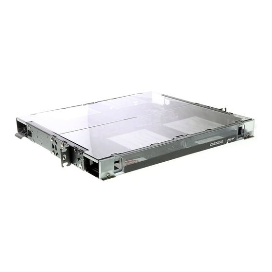
FRONT
VIEWS
CCH-01U
REAR
VIEWS
Dimensions
H: 1.75 inches
W: 17.05 inches
D: 17.06 inches
Table of Contents
1.
Precautions . . . . . . . . . . . . . . . . . . . . . . . . . . . . . . . . . . . . . . . . . . . . . . . . . . . . . . . . . . . . . . . . 2
2.
Carton Contents . . . . . . . . . . . . . . . . . . . . . . . . . . . . . . . . . . . . . . . . . . . . . . . . . . . . . . . . . . . . . 3
2.1. CCH-01U . . . . . . . . . . . . . . . . . . . . . . . . . . . . . . . . . . . . . . . . . . . . . . . . . . . . . . . . . . . . . . 3
2.2. CCH-02U . . . . . . . . . . . . . . . . . . . . . . . . . . . . . . . . . . . . . . . . . . . . . . . . . . . . . . . . . . . . . . 4
2.3. CCH-03U . . . . . . . . . . . . . . . . . . . . . . . . . . . . . . . . . . . . . . . . . . . . . . . . . . . . . . . . . . . . . . 4
3.
Tools and Materials Required . . . . . . . . . . . . . . . . . . . . . . . . . . . . . . . . . . . . . . . . . . . . . . . . . . 4
3.1. Tools . . . . . . . . . . . . . . . . . . . . . . . . . . . . . . . . . . . . . . . . . . . . . . . . . . . . . . . . . . . . . . . . . . 4
3.2. Materials . . . . . . . . . . . . . . . . . . . . . . . . . . . . . . . . . . . . . . . . . . . . . . . . . . . . . . . . . . . . . . 4
STANDARD RECOMMENDED PROCEDURE 003-876 | ISSUE 1 | January 2012 | PAGE 1 OF 21
Instruction, Closet Connector Housings (CCH) 1u/2u/3u Quick Start Guide
Instruction, Lock Kit for Closet Connector Housings
Instruction, Splice Cassette (CCH-CS) and Slack Cassette (CCH-CF) for Closet
Connector Housings
Instruction, CCH recess Mount Kit
Instruction, CCH Connector Panel
Closet Connector Housings
(CCH) 1u/2u/3u
p/n 003-876, Issue 1
CCH-02U
H: 3.5 inches
W: 17.05 inches
D: 17.06 inches
CCH-03U
H: 5.25 inches
W: 17.05 inches
D: 17.06 inches
TPA-3975
Advertisement
Table of Contents


Need help?
Do you have a question about the CCH-01U and is the answer not in the manual?
Questions and answers