Advertisement
Quick Links
related literature |Search www.corning.com/opcomm. Click on "Resources."
003-794-AEN
003-888-AEN
003-276-AEN
003-991-AEN
003-892-AEN
003-1049-AEN
000-274-AEN
003-885-AEN
006-407-QSG-AEN
1.
GENERAL
The fiber zone box (FZB) may be equipped with EDGE™ or EDGE8™ module trays. Installation of
modules is the same for either tray.
2.
TOOLS AND MATERIALS
• Panel-lifter (suction cup for laminate panels or hook-and-loop for carpeted panels) for
accessing the raised floor.
• Screwdriver and other standard tools (pliers, etc.)
• Mounting hardware is not provided. The type of hardware used depends on the mounting
location; wall anchors may be required for adequate support on sheetrock walls.
3.
GAINING ACCESS TO THE FIBER ZONE BOX (FZB)
3.1. To Open the Door
Step 1:
Unlock the door, then remove the key.
Step 2:
Pull the latch handle up and turn it one-quarter turn as shown in Figure 2.
EDGE™ Solution
EDGE Solution with 1U/2U/4U Fixed Trays
EDGE Secure Solutions FTTD Module
EDGE Port Replication Housing
EDGE and EDGE8® Solution Single Module Housing
EDGE Solution Single Module Housing for Splicing
EDGE Splice Cassette/EDGE Field-Terminated Cassette
EDGE Solution Modules in an Enhanced Management Frame
Field Tool for MTP® PRO Connectors Quick Start Guide
STANDARD RECOMMENDED PROCEDURE 003-825-AEN | ISSUE 7 | NOVEMBER 2020 | PAGE 1 OF 11
EDGE™ and EDGE8®Fiber
Zone Boxes
p/n 003-825-AEN, Issue 7
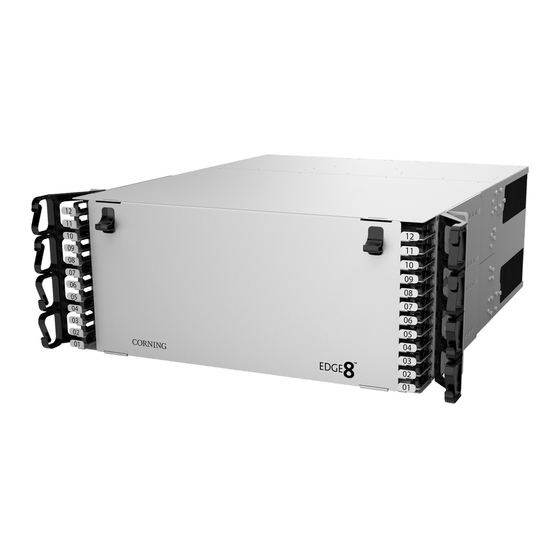
Figure 1
Advertisement

Related Manuals for CORNING EDGE


Summary of Contents for CORNING EDGE
- Page 1 Field Tool for MTP® PRO Connectors Quick Start Guide GENERAL Figure 1 The fiber zone box (FZB) may be equipped with EDGE™ or EDGE8™ module trays. Installation of modules is the same for either tray. TOOLS AND MATERIALS • Panel-lifter (suction cup for laminate panels or hook-and-loop for carpeted panels) for accessing the raised floor.
- Page 2 Remove the two packing screws next to the latches to enable the inner tray to be removed; then lift the four latches on the inner plate. Lift the plate out of the box. Note: The FZB may have either the EDGE™ or the EDGE8™ module trays installed. 3.3. To Remove the Door...
-
Page 3: Mounting The Cabinet
MOUNTING THE CABINET 4.1. To a Wall Step 1: Install (4) supplied wall-mounting brackets to cabinet using provided screws (Figure 1). Step 2: Determine the mounting location. Select a flat vertical surface for mounting to prevent warping. IMPORTANT: Make sure there is adequate space for the door to open without interference. Step 3: Use a pencil to mark the wall through the holes in the mounting brackets. -
Page 4: Alternative Method
Step 4: Reinstall all floor tiles with the panel-lifter tool. Ensure tiles are even with adjacent tiles. If the floor tile over the FZB will not lay flat and even, it may be necessary to install the box below the stringers as described in Section 4.2.3. Figure 6 4.2.2 Alternative Method 1 If unable to successfully install the unit under a raised floor following the instructions in Section 4.2.1:... - Page 5 Step 2: Position the trim plate into the gap between the stringer and the FZB. Reinstall the trim plate to the side of the unit with the provided screws (Figure 7 inset). (It may require two people to perform this operation.) Step 3: Reinstall all floor tiles with the panel-lifter tool.
- Page 6 Step 3: Determine mounting location of FZB in the ceiling and remove two ceiling panels or tiles (Figure 9). Figure 9 Step 4: Measure distance to building “red-iron” or other structural or supporting elements. Use this measurement, plus any slack length required for tieing the wire or installing nuts on threaded rod, to determine the length of each of the four support wires or rods.
- Page 7 Step 8: Pass the supporting tie wires or threaded rods through the mounting brackets (Figure 11). If using wire, simply pass the wire through the hole in the mounting bracket, loop back up, and make several wraps around the wire. Step 9: Adjust the tension by bending the wire with a pair of pliers.
-
Page 8: Installing Modules
INSTALLING MODULES NOTE: The FZB may have either the EDGE™ or the EDGE8™ module trays installed. For illustrative purposes, EDGE modules are shown in the remainder of the instruction. Step 1: The module frame can be tilted to provide better access for module or panel installation, if desired. - Page 9 Step 4: If the inner plate was removed from the box to a work surface, return the plate to the box and secure it with the latches seen in Figure 2 before installing the feeder trunk cables. Step 5: Before installing trunk cables, lift cable access panels as shown in Figure 15. Figure 15 Step 6: Install the trunk cables in the cradles per bullets 1 and 2 of Figure 16.
- Page 10 Remove dust cover from the MTP® adapter. Also remove the MTP connector dust cap by pulling on the dust cap while holding the connector body. For the initial mating, do not clean or scope connectors. Corning® CleanAdvantage™ connectors are shipped with an optimized dust cap to maintain cleanliness for the first use.
-
Page 11: Installation Options
800-743-2675 • FAX: 828-325-5060 • International: +1-828-901-5000 • www.corning.com/opcomm Corning Optical Communications reserves the right to improve, enhance, and modify the features and specifications of Corning Optical Communications products without prior notification. A complete listing of the trademarks of Corning Optical Communications is available at www.corning.com/opcomm/trademarks. All other trademarks are the properties of their respective owners.
Need help?
Do you have a question about the EDGE and is the answer not in the manual?
Questions and answers