Table of Contents
Advertisement
Quick Links
related literature |
SRP-003-1002, EDGE8™ Solution
Table of Contents
General . . . . . . . . . . . . . . . . . . . . . . . . . . . . . . . . . . . . . . . . . . . . . . . . . . . . . . . . . . . . . . . . . . . . 1
1.
2.
Precautions . . . . . . . . . . . . . . . . . . . . . . . . . . . . . . . . . . . . . . . . . . . . . . . . . . . . . . . . . . . . . . . . . 2
3.
Tools and Materials . . . . . . . . . . . . . . . . . . . . . . . . . . . . . . . . . . . . . . . . . . . . . . . . . . . . . . . . . . . 2
Connector and Adapter Cleaning . . . . . . . . . . . . . . . . . . . . . . . . . . . . . . . . . . . . . . . . . . . . . . . . 2
4.
5.
The Functionality of the Tap Module Splitters . . . . . . . . . . . . . . . . . . . . . . . . . . . . . . . . . . . . . . . 3
6.
Installing EDGE8™ MTP Tap Modules . . . . . . . . . . . . . . . . . . . . . . . . . . . . . . . . . . . . . . . . . . . . 4
7.
Referencing the Test Equipment for an MTP Tap Module . . . . . . . . . . . . . . . . . . . . . . . . . . . . . . 4
8.
Testing the Live Portion of the System . . . . . . . . . . . . . . . . . . . . . . . . . . . . . . . . . . . . . . . . . . . . 6
9.
Testing the Tap Portions of the System . . . . . . . . . . . . . . . . . . . . . . . . . . . . . . . . . . . . . . . . . . . . 9
10.
Simultaneous Testing of the Live and Tap Portions of an MTP Tap Module . . . . . . . . . . . . . . . 12
1.
General
1.1
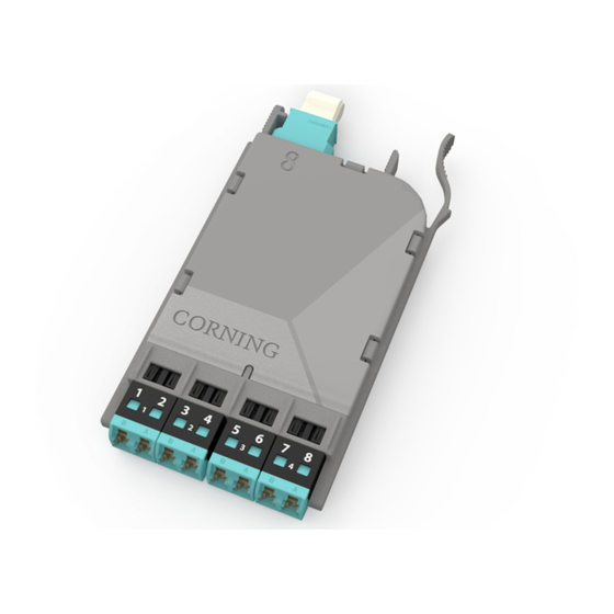
This procedure describes EDGE8™ MTP Tap
Modules, which are available for both multimode and single-mode
applications. Compatible with all EDGE8 rack-mountable
connector housings, Figure 1 shows the configurations offered.
1.2
The module contains eight fiber optic splitters which divide
the incoming optical signals into two outputs, one for live link
traffic and one for monitoring. The monitor traffic is routed via the
"TAP"-labeled MTP port to a monitoring device which filters the
data and sends it to various software tools for analysis, where it
is then viewed in application-layer software for security threats,
performance issues, or system optimization.
IMPORTANT: Please note that Tap module systems have two outputs for each input, which may
require two power meters, and depending on the system configuration, possibly require an
additional crafts person in another location when testing.
STANDARD RECOMMENDED PROCEDURE 003-139-AEN | ISSUE 1 | JANUARy 2017 | PAGE 1 OF 13
EDGE8™ MTP
Installation and Testing
003-139-AEN, Issue 1
Pinned
Non-pinned
HPA-0997-EDGE8
TAP Module
®
Pinned
Non-pinned
Non-pinned
Figure 1
Advertisement
Table of Contents

Subscribe to Our Youtube Channel
Related Manuals for CORNING EDGE8 MTP


Summary of Contents for CORNING EDGE8 MTP
-
Page 1: Table Of Contents
EDGE8™ MTP TAP Module ® Installation and Testing 003-139-AEN, Issue 1 related literature | SRP-003-1002, EDGE8™ Solution Table of Contents General ..............1 Precautions . -
Page 2: Precautions
Precautions Laser Precautions WARNING: DO NOT use magnifiers in the presence of laser radiation. Diffused laser light can cause eye damage if focused with optical instruments. Should accidental eye exposure to laser light be suspected, arrange for an eye examination immediately. Cable Handling Precautions CAUTION: Fiber optic cable is sensitive to excessive pulling, bending, and crushing forces. -
Page 3: The Functionality Of The Tap Module Splitters
Connector and Adapter Cleaning Cleaning the LC adapters with an LC port cleaner before each mating is recommended (Figure 2). Figure 2 HPA-0738 The use of an MTP Connector and Port Cleaning Tool to clean MTP connectors and ports before each mating is recommended (Figure 3). HPA-0754 Figure 3 The Functionality of the Tap Module Splitters... -
Page 4: Installing Edge8™ Mtp Tap Modules
ER transceivers (up to 40 KM). Installing EDGE8™ MTP Tap Modules EDGE8 MTP Tap modules are installed just like their normal EDGE8 module counterparts. Refer to the Installation chapter in SRP 003-1002, EDGE8 Solution, for complete instructions. This chapter covers module installation, trouble shooting, and other module-related topics as well. - Page 5 multimode only adapter Step 6: Clean and install an LC to LC Reference jumper- Reference Jumper Jumper no. 2 no. 2 (RJ2) into M1 and the LC adapter (Figure 7). Do NOT Do NOT 0.15 dB disconnect disconnect Light Source HPA-0759 Figure 7 Step 7:...
-
Page 6: Testing The Live Portion Of The System
Testing the Live Portion of the System This section describes how to calculate the loss budgets of the LIVE portion of a system using an EDGE88 MTP Tap Module and how to test that portion of the system. Note that you will need to calculate one loss budget for the LIVE system (Figure 9). - Page 7 Test harness LC #8 Note: Fiber loss RJ1 and adapter depends on length EDGE8 Module “B” of system “Near end” Do NOT EDGE8 MTP Tap Module “A” 0.00 dB Do NOT disconnect disconnect Light “Far end” Source HPA-0999-EDGE8 Figure 10...
- Page 8 Do NOT disconnect Note: Fiber loss depends on length EDGE8 Module “B” of system Do NOT EDGE8 MTP Tap Module “A” disconnect 0.00 dB Light Source “Far end” HPA-1001-EDGE8 Figure 11 Note that steps 8.4 and 8.6 can be combined if using an optical test set with both a source and a meter on one unit.
-
Page 9: Testing The Tap Portions Of The System
Testing the Tap Portions of the System NOTE: Testing of the TAP portions of a system is not required by Corning to obtain the extended warranty. The testing of the LIVE link confirms the post-installation condition of the of the trunk since the module itself is factory-tested and is not deployed like a trunk. - Page 10 9.3. Table 4 provides a complete guide to the test sequence with a light source and test harness at the front-mounted TAP MTP connector and a meter and test harness at the front-mounted TAP MTP connector of the system shown in Figure 14. Source LC Position at LIVE port test Meter # 1 and TAP port test harness “A”...
- Page 11 Do NOT EDGE8 Module “B” of system disconnect 0.00 dB “Near end” EDGE8 MTP Tap Module “A” Light Source “Far end” HPA-1005-EDGE8 Figure 15 Note steps 9.4 and 9.6 CANNOT be combined if using an optical test set with both a source and a meter in one unit.
-
Page 12: Simultaneous Testing Of The Live And Tap Portions Of An Mtp Tap Module
LC #8 Do NOT disconnect Note: Fiber loss Do NOT depends on length EDGE8 Module “B” of system disconnect 0.00 dB EDGE8 MTP Tap Module “A” Light TAP port LC #2 Source test harness “Far end” “Near end” LC #8 adapter... - Page 13 A complete listing of the trademarks of Corning Optical Communications is available at www.corning.com/opcomm/trademarks. All other trademarks are the properties of their respective owners. Corning Optical Communications is ISO 9001 certified. © 2017 Corning Optical Communications. All rights reserved.
Need help?
Do you have a question about the EDGE8 MTP and is the answer not in the manual?
Questions and answers