Table of Contents
Advertisement
Quick Links
related literature | Search www.corning.com/opcomm. Click on "Resources."
003-1002
Table of Contents
General . . . . . . . . . . . . . . . . . . . . . . . . . . . . . . . . . . . . . . . . . . . . . . . . . . . . 1
1.
2.
Precautions . . . . . . . . . . . . . . . . . . . . . . . . . . . . . . . . . . . . . . . . . . . . . . . . . . . . . . . . . . . . . . . . . 2
2.1
Laser Precautions . . . . . . . . . . . . . . . . . . . . . . . . . . . . . . . . . . . . . . . . . . . . . . . . . . . . . . . . 2
2.2
Cable Handling Precautions . . . . . . . . . . . . . . . . . . . . . . . . . . . . . . . . . . . . . . . . . . . . . . . . 2
3.
Tools and Materials . . . . . . . . . . . . . . . . . . . . . . . . . . . . . . . . . . . . . . . . . . . . . . . . . . . . . . . . . . . 2
4.
Connector and Adapter Cleaning . . . . . . . . . . . . . . . . . . . . . . . . . . . . . . . . . . . . . . . . . . . . . . . . 2
5.
Calculating System Loss Budgets . . . . . . . . . . . . . . . . . . . . . . . . . . . . . . . . . . . . . . . . . . . . . . . . 3
6.
The Functionality of the Tap Module Splitters . . . . . . . . . . . . . . . . . . . . . . . . . . . . . . . . . . . . . . . 5
7.
Installing an EDGE8™ LC-MTP Tap Module . . . . . . . . . . . . . . . . . . . . . . . . . . . . . . . . . . . . . . . . 5
8.
Referencing the Test Equipment for an LC-MTP Tap Module . . . . . . . . . . . . . . . . . . . . . . . . . . . 5
9.
Testing EDGE8 LC-MTP Tap Modules . . . . . . . . . . . . . . . . . . . . . . . . . . . . . . . . . . . . . . . . . . . . 7
1.
General
1.1
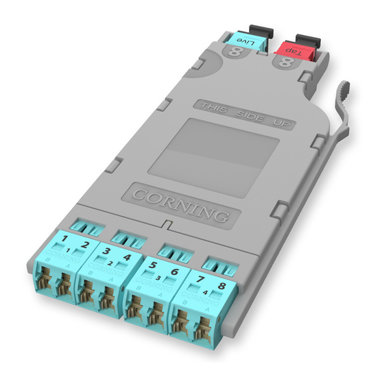
This procedure describes EDGE8™ LC-MTP
Tap Modules, which are available for both
multimode and single mode applications.
Compatible with all EDGE8 rack-mountable
connector housings, LC-MTP Tap modules have
twelve front-mounted shuttered LC adapters
and two rear-mounted MTP connectors
(Figure 1).
1.2
The module contains 12 fiber optic splitters
which divide the incoming optical signals into
two outputs, one for live link traffic and eight
for monitoring. The monitor traffic is routed
via the "TAP"-labeled MTP connector to a
monitoring device which filters the data and sends it to various software tools for analysis, where
it is then viewed in application-layer software for security threats, performance issues, or system
optimization.
IMPORTANT: Please note that Tap module systems have two outputs for each input, which may require
two power meters, and depending on the system configuration, possibly require an additional craftsperson
in another location.
STANDARD RECOMMENDED PROCEDURE 003-137-AEN | ISSUE 1 | JANUARy 2017 | PAGE 1 OF 8
EDGE8
Solution
™
EDGE8
LC-MTP
™
Module Installation and
Testing
003-137-AEN, Issue 1
HPA-0753-EDGE8
Tap
®
Figure 1
Advertisement
Table of Contents

Related Manuals for CORNING EDGE8 LC-MTP


Summary of Contents for CORNING EDGE8 LC-MTP
- Page 1 Testing EDGE8 LC-MTP Tap Modules ........
- Page 2 Precautions Laser Precautions WARNING: DO NOT use magnifiers in the presence of laser radiation. Diffused laser light can cause eye damage if focused with optical instruments. Should accidental eye exposure to laser light be suspected, arrange for an eye examination immediately. Cable Handling Precautions CAUTION: Fiber optic cable is sensitive to excessive pulling, bending, and crushing forces.
- Page 3 Calculating System Loss Budgets This section describes how to calculate the loss budgets of a system using an EDGE8™ Tap Module. Note that you will need to calculate one loss budget for the LIVE system (Figure 4) and two different loss budgets for the Tap output (Figure 5 and 6). Table 1 indicates the system loss values of the system components: Multimode Fiber Single-Mode Fiber...
- Page 4 Budget loss for a “Near end” Tap port test harness multimode system using OM4 fiber and 50/50 splitters: 0.15 +3.7 + 0.30 + 0.10 = 4.25 dB + fiber loss LC mated 50/50 pair splitter 0.15 3.70 mated pair 0.30 Note: Fiber loss depends on length of system...
- Page 5 The Functionality of the Tap Module Splitters Directionality In simplest terms, the splitters inside a Tap module act like a divider of a one-way traffic flow – in this case, light. Input into LIVE LC # 2 output The even-numbered LC connectors in a Tap module serve only for source input and their traffic is split between the LIVE and output...
- Page 6 To reference the source and two meters: 22 mm mandrel wrap for multimode only Step 1: Clean and insert the SC-end of the SC to LC jumper (Reference Jumper no. 1, or RJ1) into the Reference output of the light source. Do NOT Jumper no.1 disconnect...
- Page 7 IMPORTANT: From this step on, do NOT disconnect the connectors on either the Light Source or meter port adapters. Testing EDGE8 LC-MTP Tap Modules Table 2 provides a complete guide to the testing sequence for testing with the light source at the Tap module “A”...
- Page 8 A complete listing of the trademarks of Corning Optical Communications is available at www.corning.com/opcomm/trademarks. All other trademarks are the properties of their respective owners. Corning Optical Communications is ISO 9001 certified. © 2017 Corning Optical Communications. All rights reserved.
Need help?
Do you have a question about the EDGE8 LC-MTP and is the answer not in the manual?
Questions and answers