Intermec Trakker Antares 2400 User Manual
Handheld terminal
Hide thumbs
Also See for Trakker Antares 2400:
- User manual (118 pages) ,
- Quick start manual (9 pages) ,
- Quick reference manual (2 pages)
Table of Contents
Advertisement
Quick Links
Download this manual
See also:
Quick Reference Manual
This manual contains information about the terminal's features, installing the terminal, learning about
the menu system, operating the terminal in a network, and troubleshooting problems.
If you need to learn how to configure the terminal, develop and use applications, run diagnostics, use
reader commands and configuration commands, or use default and optional applications, you also need to
download the
Trakker Antares 2400 Family System Manual
Myriad Pro Black
AGaramond
Read This First!
(P/N 071389).
Advertisement
Table of Contents
Troubleshooting

Related Manuals for Intermec Trakker Antares 2400


Summary of Contents for Intermec Trakker Antares 2400
-
Page 1: Read This First
If you need to learn how to configure the terminal, develop and use applications, run diagnostics, use reader commands and configuration commands, or use default and optional applications, you also need to download the Trakker Antares 2400 Family System Manual Read This First! (P/N 071389). - Page 2 User's Manual Trakker Antares ® 242X Handheld Terminal...
- Page 3 User's Manual ® Trakker Antares 242X Handheld Terminal...
- Page 4 The information contained herein is proprietary and is provided solely for the purpose of allowing customers to operate and service Intermec-manufactured equipment and is not to be released, reproduced, or used for any other purpose without written permission of Intermec.
- Page 5 Document Change Record This page records changes to this document. The document was originally released as version 001. Version Date Description of Change 7/1997 This manual was changed to add information about the TRAKKER Antares 2420 terminal and to document the new firmware version. The new information includes: the TRAKKER Antares 2420 terminal and features, RS- 232 serial communications on the TRAKKER Antares 2425 terminal, TRAKKER Antares firmware version 2.10, multiple drives and applications on the TRAKKER...
- Page 6 Important Data Collection Browser Information Sheet (P/N 070012-002). Removed these documents, because this information is included in the system manual: the Trakker Antares 2400 Family User’s Manual Addendum (P/N 070451), the Trakker Antares 2400 Family Firmware V6.15 Instruction Sheet (P/N 071388), and the Trakker Antares 2400 Family Firmware V6.20 Instruction Sheet (P/N 071867).
-
Page 7: Table Of Contents
Contents Before You Begin...ix Safety Summary...ix Safety Icons ...x Global Services and Support ...xi Who Should Read This Document? ... xii Related Documents ... xii Learning About the Terminal What Are the Trakker Antares 242X Terminals?... 2 Learning About the Terminal’s Features ... 3 Options for the Terminals ... - Page 8 Choosing a Communications Protocol ... 52 Using RF Communications on the 2425 ... 55 Planning the Network Connection ... 55 Configuring the Intermec Gateway or DCS 30X ... 56 Configuring the Access Points... 57 Configuring the 2425 Network Parameters... 58 Configuring the 802.1x Security Parameters ...
- Page 9 Problems With RF Connectivity (2425 only) ... 75 Problems While Running Applications ... 77 Problems Transmitting Data Through the Serial Port... 78 Problems Transmitting Data Through the Intermec Gateway or DCS 30X ... 79 Problems Scanning Bar Code Labels ... 79 Guidelines for Managing Batteries ... 82 Booting the Terminal ...
- Page 10 Contents viii Trakker Antares 242X Handheld Terminal User’s Manual...
-
Page 11: Before You Begin
Safety Summary Your safety is extremely important. Read and follow all warnings and cautions in this document before handling and operating Intermec equipment. You can be seriously injured, and equipment and data can be damaged if you do not follow the safety warnings and cautions. -
Page 12: Safety Icons
Before You Begin Safety Icons This section explains how to identify and understand dangers, warnings, cautions, and notes that are in this document. You may also see icons that tell you when to follow ESD procedures and when to take special precautions for handling optical parts. -
Page 13: Global Services And Support
Global Services and Support Warranty Information To understand the warranty for your Intermec product, visit the Intermec web site at http://www.intermec.com and click Service & Support. The Intermec Global Sales & Service page appears. From the Service & Support menu, move your pointer over Support, and then click Warranty. -
Page 14: Who Should Read This Document
Trakker Antares 2420 and 2425 handheld terminals, and how to install, configure, operate, maintain, and troubleshoot them. Use this manual in conjunction with the Trakker Antares 2400 Family System Manual (P/N 071389), which contains detailed information about configuring, operating, and programming all terminals in the 2400 Family. -
Page 15: Learning About The Terminal
Learning About the Terminal ® This chapter introduces the Trakker Antares 2420 and 2425 handheld terminals and their features including the batteries, memory, drives, and input devices. It also describes how to start using the 242X. This chapter covers these topics: •... -
Page 16: What Are The Trakker Antares 242X Terminals
The 2425 is also supported by the Wavelink Avalanche client management system. For more information, see Chapter 2, “Configuring and Managing the Terminals,” in the Trakker Antares 2400 Family System Manual (P/N 071389). The 2425 with an IEEE 802.11b radio installed is Wi-Fi certified for interoperability with other 802.11b wireless LAN devices. -
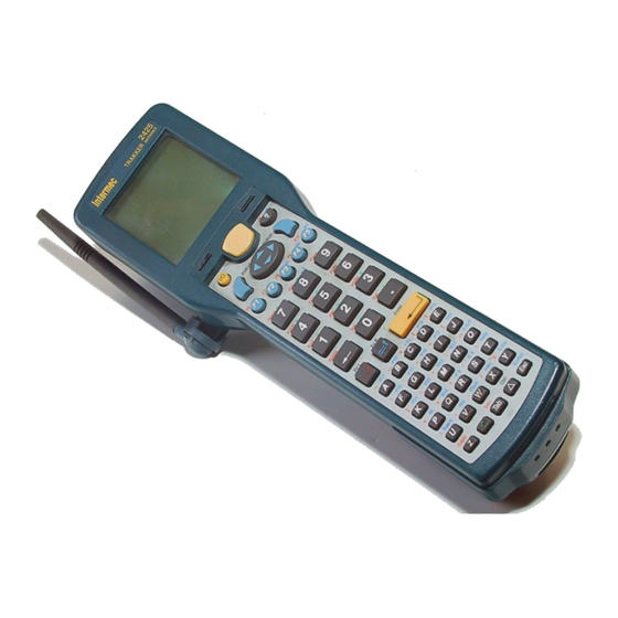
Page 17: Learning About The Terminal's Features
nugget Learning About the Terminal’s Features The 242X is designed to make data collection easy and includes the following features. Scan module, serial module, or input device module Antenna (2425 only) 242X features: This illustration points out the key features of the 242X. See the next table for a description of each feature. -
Page 18: Options For The Terminals
Data Collection Browser (dcBrowser) application • Trakker Antares ROM-DOS™ support • UDP Plus (Intermec Gateway or DCS 30X network), WTP (Intermec Gateway or DCS 30X network), or TCP/IP (direct connect to host) network protocol • WLI Forum OpenAir radio or IEEE 802.11b radio... -
Page 19: Accessories For The Terminal
nugget For additional help using dcBrowser, see the online help that ships with the dcBrowser gateway software, or see the Data Collection Browser Client User’s Guide (P/N 070011). Accessories for the Terminal You can use the following accessories (sold and ordered separately) with the terminals. -
Page 20: What's New
Chapter 1— Learning About the Terminal 242X Accessories (continued) Accessory AC power supply Handle Serial Interface Module Input Device Module Standard Range Scan Module Long Range Scan Module Advanced Long Range Scan Module High Visibility Scan Module High Density Scan Module PDF417 Laser Scan Module... -
Page 21: Using The Terminal For The First Time
• Information from the Trakker Antares 2400 Family System Manual Addendum was incorporated: 802.1X security enhancements to provide new functionality to the current TTLS security and support for Cisco’s LEAP security. For more information, see “Configuring the 802.1x Security Parameters” on page 59. -
Page 22: Unpacking The Terminal
Check the contents of the box against the invoice for completeness and contact your local Intermec service representative if there is a problem. Learning About the Terminal’s Batteries The 242X uses two rechargeable batteries: •... -
Page 23: Charging The Main Battery Pack
nugget Charging the Main Battery Pack You need to fully charge the battery pack before you can use the terminal. To charge the main battery pack • Place the battery pack in an empty slot in the battery charger. The battery pack is fully charged in about 2 hours. - Page 24 Chapter 1— Learning About the Terminal Disconnect the battery pack from the connectors inside the bottom case by sliding the battery pack toward the bottom end of the terminal. Tilt the terminal to one side and let the battery pack drop out of the compartment into your hand.
-
Page 25: Learning About The Backup Battery
nugget 3 Hook the bottom edge of the battery door into the bottom case above the backup battery compartment. Push the door down to close it over the battery compartment. Push the battery door latch down and slide it toward the top end of the terminal to lock the door in place. Learning About the Backup Battery When you replace the backup battery, all data stored in RAM is lost. -
Page 26: Charging The Backup Battery
However, you can remove and replace the backup battery if it will no longer hold a charge, or if the battery is dead. Contact your local Intermec service representative to order a new backup battery. - Page 27 nugget 3 Open the battery door by pushing down on the battery door latch and sliding it toward the bottom end of the terminal. Lift up the top edge of the battery door to remove it. Note: If you have a handstrap installed, stretch the handstrap’s elastic band to allow the T-bar to slide out of the T-bar opening on the bottom end of the terminal.
- Page 28 Chapter 1— Learning About the Terminal To install a backup battery 1 Slide the backup battery into the lower half of the battery compartment. The wired end of the backup battery should be visible in the compartment. 2 Firmly push together the backup battery wire connector and the terminal wire connector until they lock.
-
Page 29: Disposing Of The Nicad Backup Battery
Disposing of the NiCad Backup Battery The materials used in the construction of the Trakker Antares NiCad backup battery are recyclable. Intermec strongly urges you to recycle the backup batteries when they reach the end of their useful lives. Additionally, the Environmental Protection Agency has classified worn out or damaged NiCad batteries or battery packs to be hazardous waste. -
Page 30: Managing Battery Power
Chapter 1— Learning About the Terminal Managing Battery Power To maximize the life of the terminal’s backup battery and main battery pack, use these power management features. Managing Battery Power Situation You are not using the terminal for 5 minutes or longer. -
Page 31: Finding The Special Keys
nugget English, French, German, Italian, Portuguese, and Spanish. You use special keys and key sequences to access the characters in each language. The 2425 supports a TE 2000 application for IBM 3270, IBM 5250, or IBM VT100/220/320/340 and ANSI. When you order a TE 2000 application, you also receive the appropriate TE 2000 keypad overlay. -
Page 32: Using The Suspend/Resume Key
Chapter 1— Learning About the Terminal Typing the Characters Position on the Keypad Middle of the key. Left side above the key. Centered above the key. Right side above the key. You can also use the arrow keys to move the cursor around an application screen. -
Page 33: Using The Modifier Keys
nugget Even if you change the battery pack while the terminal is turned off, the terminal resumes or boots the next time the terminal is turned on. Using the Modifier Keys The keypad does not have a physical key for every character and function available. -
Page 34: Using The Western European Keypad
Chapter 1— Learning About the Terminal 3 Type an alphabetic character. The letter appears as an uppercase character on the terminal’s screen. For example, press F to type an uppercase letter F. Caps Lock remains enabled until you disable it. To type a lowercase letter with Caps Lock enabled •... -
Page 35: Using The Te 2000 Keypads
nugget 3 There are three types of characters you can enter: • To accent a lowercase character, press the character. For example, press A to type the ä character. • To accent an uppercase character, press the ? key. Next, press the character you want to accent. -
Page 36: Learning About The Status Icons
Chapter 1— Learning About the Terminal To change the display contrast using the keypad • Press ) +. Each time you press ) +, the contrast becomes one level darker. There are eight contrast levels. If the contrast is at the darkest level and you press ) +, the contrast changes to the lightest contrast level. -
Page 37: Learning About The Audio Signals
Connected to an access Plus or connected. point, but not to an Intermec Gateway or DCS 30X. In a UDP Plus or WTP network, the Connect icon is not instantaneously updated, but it does tell you the communications status the last time data was sent or received from the 2425. For help, see Chapter 3, “Operating the Terminal in a Network.”... - Page 38 For help, see “Exiting Screens and Saving Changes” on page 41. • Use the TRAKKER Antares 2400 Menu System. From the Main Menu, choose Configuration Menu, Terminal Menu, and then Beeper. • Use the Beep Volume command. For help, see “Beep Volume” in Chapter 6 of the 2400 Family system manual.
-
Page 39: Using The Terminal's Serial Ports
nugget Using the Terminal’s Serial Ports Serial ports, also called COM (communication) ports, are locations from which data can be passed in to and out of the terminal. The 242X supports RS-232 serial communications to communicate with other serial devices, such as modems, PCs, and printers, through a COM port. -
Page 40: Using The Scan Module
Chapter 1— Learning About the Terminal Using the Scan Module Do not look directly into the window area or at a reflection of the laser beam while the laser is scanning. Long-term exposure to the laser beam can damage your vision. Attention Danger: Ne regardez pas directement la réflexion d’un rayon laser ou dans la fenêtre du laser lorsque celui-ci est en opération. - Page 41 nugget 3 Press the Scan button on the keypad. Direct the beam so that it falls across all bars in the bar code label. When the terminal successfully reads the label, you hear a high beep. 4 When the scanner laser beam is on, both scanner light emitting diodes (LEDs) at the top of the keypad are lit in a yellow color.
-
Page 42: Scanning Options
Chapter 1— Learning About the Terminal • Optimum scan angles vary with the type and print quality of the bar code label, the distance of the scanner from the label, and the lighting in the area. • Do not scan the bar code label “straight on.” In a 2-degree conical “dead zone”... -
Page 43: Connecting To A Serial Device Or Network
nugget For more information about these commands, see Chapter 6, “Configuration Command Reference,” in the 2400 Family system manual. Connecting to a Serial Device or Network You can communicate with other RS-232 devices, such as modems, PCs, and printers, through a COM port by: •... - Page 44 Chapter 1— Learning About the Terminal 2420 Drive C Drive D or font set Drive E Drive G Drive C Drive C is a 2MB flash drive. You can use up to 750K of this flash drive to store up to 128 files on drive C. Applications must be stored on drive C. You use standard ANSI C library interface definitions to access the information on this drive.
- Page 45 39 AGaramond nugget Chapter 1— Learning About the Terminal Drive G Drive G is an optional 2MB or 4MB extended storage drive that is available for the 2420. You can store up to 128 files on drive G. Use this drive to store large lookup tables and data files.
- Page 46 39 AGaramond nugget Chapter 1— Learning About the Terminal Trakker Antares 242X Handheld Terminal User’s Manual...
-
Page 47: Configuring The Terminal
This chapter describes the different methods that you can use to configure the 242X and its memory and drives. It also explains how to configure the terminal using the TRAKKER Antares 2400 Menu System. This chapter covers these topics: • How to configure the terminal •... -
Page 48: How To Configure The Terminal
You can configure the terminals by using any of the following methods. Use the TRAKKER Antares 2400 Menu System You can use the menus and screens of the TRAKKER Antares 2400 Menu System to view the current configuration and change the configuration parameters. -
Page 49: About The Configurations
The TRAKKER Antares 2400 Menu System lets you configure the terminal, manage files, view system information, and run diagnostics. You can access the TRAKKER Antares 2400 Menu System while running any application. When you are using the menu system, you may not see a parameter until you set a value for another key field. - Page 50 Chapter 2— Configuring the Terminal To access the TRAKKER Antares 2400 Menu System • Press ) y 2 4 8, or scan this bar code: TRAKKER Antares 2400 Menu System *..-.* *..-.* The Main Menu appears, displaying four menu options.
- Page 51 Access Point App Efficiency Serial Port Test Malloc Info Menu Code Verify The TRAKKER Antares 2400 Menu System at a Glance Trakker Antares 242X Handheld Terminal User’s Manual Chapter 2— Configuring the Terminal CONFIGURATION MENU Symbologies Menu Symbology IDs Menu...
-
Page 52: Accessing Online Help
Main Menu, you can press [ or { to select a menu, and then press ;, y, or z. Note: In the TRAKKER Antares 2400 Menu System, the ;, y, and z keys all work the same way. Configuration Menu... -
Page 53: Marking Check Boxes
nugget PRIMARY NETWORK Activate: Disabled Host IP Addr: 0.0.0.0 Terminal IP Address: 0.0.0.0 Toggle and Entry Fields: For example, the Primary Network screen has toggle and entry fields. The Activate field is a toggle field. Press « to toggle between Disabled and 802.11 DS or OpenAir. -
Page 54: Entering Ascii Control Characters
Entering ASCII Control Characters You can include ASCII control characters in a postamble or preamble by using the TRAKKER Antares 2400 Menu System. For a definition of the postamble or preamble, see Chapter 6, “Configuration Command Reference,” in the 2400 Family system manual. -
Page 55: Exiting Screens And Saving Changes
Exiting the Menu System 1 Press d until you exit the TRAKKER Antares 2400 Menu System. If you have made any changes to the current configuration, the next screen prompts you to save the configuration parameters that are currently enabled on the terminal to RAM. - Page 56 5 Choose Yes and press ; to save your changes in flash memory. The terminal saves the current configuration as the active configuration. The Exiting TRAKKER Antares 2400 Menu System screen appears. Choose No and press ; to exit without saving. The terminal continues to use your changes until you boot or reset the terminal.
-
Page 57: Configuring Drives And Memory On The Terminal
TRAKKER Antares 2400 6 Choose OK and press ; to exit the TRAKKER Antares 2400 Menu System. Choose Cancel and press ; to return to the Main Menu. After you exit the menu system, the terminal will resume the application you were running when you started the menu system. -
Page 58: Configuring Flash Memory
Chapter 2— Configuring the Terminal Note: When you boot or reset the terminal, all files on the RAM drive are destroyed. For help configuring the RAM drive, see “RAM Drive Size” in Chapter 6 of the 2400 Family system manual. Configuring Flash Memory If you ordered the optional 4MB flash memory drive, you have an additional 2MB of extended flash memory. -
Page 59: Operating The Terminal In A Network
This chapter describes how to install and configure the 242X in a serial or RF network. It also explains how the 242X fits into a particular network and how to use serial or RF network communications. This chapter covers these topics: •... -
Page 60: How The Terminals Fit Into Your Network
Chapter 3— Operating the Terminal in a Network How the Terminals Fit Into Your Network The 2420 and 2425 are versatile handheld terminals that you can easily add to your network or distributed data collection system. You can use the 2420 and the 2425 as end devices in your wired network. The terminals have a serial port to transmit data to and receive data from a host computer or PC through RS-232 serial communications. - Page 61 You can use the serial port to connect to a 900 MHz RF network using the 9189 RF Gateway. The terminal communicates with the 900 MHz RF network using Polling Mode D protocol. 242X in a 900 MHz RF Network Trakker Antares 242X Handheld Terminal User’s Manual Chapter 3—...
- Page 62 Chapter 3— Operating the Terminal in a Network TCP/IP Direct Connect Network In a TCP/IP network, the 2425 communicates with a host computer directly using TCP/IP for the RF protocol. The access point acts as a bridge between the wired network and the RF network. UDP Plus or WTP Network In a UDP Plus or WTP network, the 2425 communicates with a host computer through the G4000.
- Page 63 Multiple Subnetworks (UDP Plus) In a UDP Plus network, you can install the 2425s, access points, and the G4000 as shown in the next illustration. All the terminals and access points in this illustration communicate with the G4000 at IP address 192.9.175.7.
- Page 64 Chapter 3— Operating the Terminal in a Network Multiple Subnetworks (TCP/IP) In a TCP/IP network, you can install the 2425s and access points as shown in the next illustration. All the terminals and access points in this illustration communicate with the host at IP address 192.9.175.7. If you are using MobileLAN access points, a terminal can roam across subnetworks.
-
Page 65: Using Serial Communications On The Terminal
Communicating Across Subnetworks (UDP Plus) You can install 2425s and access points in one subnetwork and install the G4000 or host in another subnetwork. If the 2425s are communicating across a subnetwork, you must configure additional network parameters (default router and subnet mask). The next illustration shows the G4000 in another subnetwork from the terminals. -
Page 66: Choosing A Communications Protocol
• Flow control Configurable Protocol Configurable protocol is based on Intermec’s Polling Mode D protocol except that you have the option to change some of the serial port protocol parameters or remove specific events from the protocol, such as poll or handshake. -
Page 67: Master Polling Protocol
You can configure the following serial port parameters: • Baud rate • Data bits • Parity • Stop bits • Flow control • EOM (End of Message) • Configuration commands via serial port • LRC • SOM (Start of Message) •... -
Page 68: Point-To-Point Protocol
Chapter 3— Operating the Terminal in a Network Before each transmit operation, the terminal issues the SEL sequence for the device addressed and sends the data if an acknowledge is received. Before each receive operation, the terminal issues a poll sequence and waits for data or the RES character (no data is available to send). -
Page 69: Using Rf Communications On The 2425
2400 Family System Manual (P/N 071389). The set of network parameters you must configure depends on whether you install the terminal on the same subnetwork as the Intermec Gateway or DCS 30X (UDP Plus or WTP) or host (TCP/IP) or on a different subnetwork. -
Page 70: Configuring The Intermec Gateway Or Dcs 30X
DCS 30X through the access points connected to the Ethernet network. For more information, see the appropriate TE 2000 manual. Note: You can use a 2425 running TCP/IP and the Intermec Gateway or DCS 30X in a pass-through network. You establish a direct TCP/IP socket connection from the 2425 to the host through the server. -
Page 71: Configuring The Access Points
If you are using a DHCP (Dynamic Host Configuration Protocol) server in a UDP Plus or TCP/IP network, you can leave the default terminal IP address as 0.0.0.0 to enable the 2425 as a DHCP client. For help, see “DHCP (Terminal)” in Chapter 6 of the 2400 Family system manual. -
Page 72: 802.11B Radio
The set of network parameters you must configure depends on whether you install the terminal on the same subnetwork as the Intermec Gateway, DCS 30X, or host (TCP/IP) or on a different subnetwork. You need to configure: •... -
Page 73: Configuring The 802.1X Security Parameters
• Terminal IP Address (Non-DHCP environment only). • Network Port. • Default Router (Intermec Gateway, DCS 30X, or host on different subnetwork). • Subnet Mask (Intermec Gateway, DCS 30X, or host on different subnetwork). For help understanding these parameters and their syntax, see Chapter 6, “Configuration Command Reference,”... -
Page 74: Configuring 802.1X Ttls Security
• your terminal is configured with the primary network, advanced network, and radio parameters. 2 Set the User Name and Password parameters. Scan this bar code label to access the TRAKKER Antares 2400 Menu System: TRAKKER Antares 2400 Menu System *..-.*... -
Page 75: Configuring 802.1X Leap Security
If you just want to make sure that your terminal can be authenticated, you can use the default values of “anonymous” and “anonymous.” However, Intermec recommends that you set your permanent user name and password to unique values. 3 Exit the menu system and save all changes. - Page 76 Chapter 3— Operating the Terminal in a Network To enable 802.1x LEAP security on the terminal 1 Make sure that: • your authentication server is properly configured. For help, see the documentation for your authentication server. • your Cisco access point is properly configured for LEAP security. For help, see the documentation for your Cisco access point.
-
Page 77: Monitoring Network Communications
3 On your Trakker Antares terminal, set the User Name and Password parameters. Scan this bar code to access the TRAKKER Antares 2400 Menu System: TRAKKER Antares 2400 Menu System *..-.* *..-.* The Main Menu appears. Choose Configuration Menu > Communications Menu > Radio. - Page 78 Chapter 3— Operating the Terminal in a Network Trakker Antares 242X Handheld Terminal User’s Manual...
-
Page 79: Troubleshooting And Maintaining The Terminal
This chapter lists problems you may encounter while using the terminal and provides some possible solutions. It also describes how to boot or reset the terminal, replace the antenna, and clean the screen and scan module window. This chapter covers these topics: •... -
Page 80: Problems And Solutions
You can also use the error numbers and messages table and the terminal diagnostics to help analyze and solve problems. For help, see Chapter 4, “Running Diagnostics,” in the Trakker Antares 2400 Family System Manual (P/N 071389). If you have problems with TE 2000 terminal emulation applications, see the appropriate TE 2000 manual. -
Page 81: Problems While Operating The Terminal
Chapter 4— Troubleshooting and Maintaining the Terminal Possible Solution If you are using an Intermec-labeled battery pack (P/N 068537 or P/N 073152), make sure you remove the rubber bumper from the inside of the battery door. Try closing the battery door again. - Page 82 Default Configuration *.+* *.+* You can also use the TRAKKER Antares 2400 Menu System. For help, see “Restoring the Terminal’s Default Configuration” in Chapter 2 of the 2400 Family system manual. After you load the default configuration, you may need to set the primary network communications parameters to communicate with other devices in the network.
-
Page 83: Problems While Configuring The Terminal
Network Activate command must be set to the RF network before you can save any changes to the Security ID command. If you are working in the TRAKKER Antares 2400 Menu System, you cannot scan configuration commands. Use the Configuration Menu to change the terminal’s configuration, or exit the menu... - Page 84 Chapter 4— Troubleshooting and Maintaining the Terminal Problems While Configuring the Terminal (continued) Problem You are scanning a configuration command to set one of the serial port parameters and hear three low beeps. For example, you are trying to set EOM or SOM. You scan or enter an option for the Scanner Selection configuration command and you hear three low beeps.
- Page 85 You need to change the default router address. Choose Advanced Network from the Communications Menu. The terminal and Intermec Gateway or DCS 30X (UDP Plus or WTP network), or host (TCP/IP network) are on different networks, and the terminal is not on the same network as the default router.
- Page 86 The terminal IP address or the controller/host IP address is set to 0.x.x.x or 127.x.x.x. These are invalid addresses. Set a valid IP address for the terminal and Intermec Gateway, DCS 30X, or host. For help, see “Using RF Communications on the 2425” on page 55.
-
Page 87: Problems While Configuring 802.1X Security
2400 Family system manual. This section references error numbers that are displayed on the Error Logger screen in the TRAKKER Antares 2400 Menu System. To view the Error Logger screen, from the Main Menu, choose Diagnostics Menu, Software Diagnostics, and then Error Logger. - Page 88 BASEDATE.TXT and LOADER.EXE on your PC. These files are available as part of the firmware upgrade that can be downloaded at no charge from the Intermec Web site at www.intermec.com. Follow Steps 1 through 5 of the procedure To transfer applications and files to the terminal using LOADER.EXE in Chapter 3,...
-
Page 89: Problems With Rf Connectivity (2425 Only)
2400 Family system manual. If the network is enabled and the Radio icon remains on, there may be a problem with the radio card. For help, contact your local Intermec service representative. The host may have deactivated or lost your current terminal emulation session. - Page 90 Intermec service representative. In a UDP Plus or WTP network, the terminal is communicating with an access point, but it is not connected to the Intermec Gateway or DCS 30X. You may need to check the 2425 configuration or make sure the Intermec Gateway or DCS 30X is running and that data collection is started.
-
Page 91: Problems While Running Applications
Intermec Gateway or DCS 30X and the host computer. Make sure the terminal is correctly configured for your network. In a UDP Plus or WTP network, make sure the Intermec Gateway or DCS 30X is configured and data collection is started. In a TCP/IP network, make sure the host computer is configured and running. -
Page 92: Problems Transmitting Data Through The Serial Port
SCREEN ERROR: 31 Code: 3 Hit any key To exit! You try to run a DOS application in the TRAKKER Antares 2400 Menu System and see this message: Not a valid application. Problems Transmitting Data Through the Serial Port If you are having problems sending or receiving data through the serial port on the terminal, check these possible problems: •... -
Page 93: Problems Transmitting Data Through The Intermec Gateway Or Dcs 30X
The buffer holding transactions to be sent to the controller is full. Stop collecting data with this terminal. Make sure the terminal is communicating with the Intermec Gateway or DCS 30X and let the terminal send all the transactions in the buffer before you continue collecting data. - Page 94 LEDs remain on, there may be a problem with the LEDs. Press the Scan button again without scanning a bar code label. If the LEDs are still on, contact your local Intermec service representative. The scan module window may be dirty. Clean the window of the scan module with a solution of mild soap and water.
- Page 95 LEDs remain on, there may be a problem with the LEDs. Press the Scan button again without scanning a bar code label. If the LEDs are still on, contact your local Intermec service representative. The reader commands may be disabled. Scan the Enable Override command to temporarily enable all of the reader commands.
-
Page 96: Guidelines For Managing Batteries
Chapter 4— Troubleshooting and Maintaining the Terminal Guidelines for Managing Batteries Follow these guidelines to manage the terminal batteries, prevent problems, and preserve battery power. For help charging or replacing batteries, see “Learning About the Terminal’s Batteries” on page 8. Main Battery Pack •... -
Page 97: Booting The Terminal
nugget Cold Temperatures (Using the 242X in sub-freezing environments) • If you use the terminal in a cold temperature environment, battery life will be reduced. Battery life depends on temperature, battery model, input device, age of the battery pack, your usage, and duty cycle factors. If you use the terminal for extended periods of time in sub-freezing environments, you may need to change the main battery pack more often. -
Page 98: Using The Boot Menu
You can configure the Resume Execution command by using the TRAKKER Antares 2400 Menu System or by scanning these bar code labels. For help, see Chapter 2, “Configuring the Terminal,” or see “Resume Execution”... -
Page 99: Troubleshooting A Locked Up Application
1 Press q to turn off the terminal. Press q to turn on the terminal. 2 Use the TRAKKER Antares 2400 Menu System to reboot the terminal. Press ) y 2 4 8 to enter the TRAKKER Antares 2400 Menu System. - Page 100 5 Press B to boot the terminal. Once the terminal has finished booting, your application appears. If the terminal still will not reset or boot, try loading the firmware. For help, contact your local Intermec service representative. nugget BOOT MENU...
-
Page 101: Maintaining And Cleaning The Terminal
2425. You can replace the antenna using the instructions in this section. If you have problems with other mechanical parts, contact your local Intermec service representative for help. To replace the antenna, you need these items: • 2.4 GHz SMB antenna (P/N 063825) •... - Page 102 Chapter 4— Troubleshooting and Maintaining the Terminal 2 Insert the straight-slot screwdriver into the retaining ring opening so that the screwdriver is in the retaining ring slot. 3 Pry the retaining ring up out of the opening and remove it. 4 Gently pull the antenna off the antenna connector on the 2425.
-
Page 103: Cleaning The Scan Module Window And Terminal Screen
nugget 9 Turn the 2425 over and adjust the angle of the antenna as needed. Cleaning the Scan Module Window and Terminal Screen To keep the terminal in good working order, you need to clean the scan module window and terminal screen. Clean these surfaces as often as needed or when they are dirty. - Page 104 39 AGaramond nugget Chapter 4— Troubleshooting and Maintaining the Terminal Trakker Antares 242X Handheld Terminal User’s Manual...
-
Page 105: Specifications
Specifications This appendix lists the terminal’s physical and environmental specifications and contains these topics: • Terminal dimensions • Power specifications • Electrical specifications • Temperature and environmental specifications • Screen • Keypad options • Application options • Connectivity options • Memory •... -
Page 106: Physical And Environmental Specifications
Appendix A— Specifications Physical and Environmental Specifications Terminal Dimensions Dimension Length: Height: Width: Weight: 2420 2425 Power and Electrical Specifications Power Operating: Memory Backup: Electrical Rating: Temperature and Environmental Specifications Type of Operation Operating the terminal: Operating 2420 with the modem option: Storing the terminal: Charging the battery pack: (with or without batteries installed) - Page 107 Keypad Options • Full alphanumeric keypad with 56 keys, available as an English keypad or a multilingual European language keypad • Terminal emulation keypads for TE 2000 IBM 3270, TE 2000 IBM 5250, and TE 2000 VT/ANSI Note: Terminal emulation keypads are available only in English. However, TE 2000 applications can display characters in the Western European languages.
- Page 108 Appendix A— Specifications OpenAir Radio Specifications Radio Feature Radio type Channels Data rate Range Frequency band Wired Data Communications • Optical serial communications port interface • RS-232C serial port, up to 38400 baud • (2420 modem option) Direct RJ11 phone connection, up to 33600 baud •...
-
Page 109: Terminal Cable Accessories
For a list of compatible scanner cables, see your Intermec sales representative. Intermec is frequently testing and developing new input devices. For an updated list of Intermec-approved input devices for the 242X or for help determining which cable you need, see your Intermec sales representative. Scan Module Options •... - Page 110 Appendix A— Specifications Standard Range Scan Module Optical Parameters Bar Code Specification 5.0 mil code 7.5 mil code 10 mil code 15 mil code 20 mil code 40 mil code 55 mil code 55 mil code, retroreflective 100 mil code, retroreflective Long Range Scan Module Optical Parameters Bar Code Specification 10 mil code...
- Page 111 Note: If you are using the advanced long range scan module, you may not be able to scan the bar code labels in this manual. However, you can still send commands through the serial port or network. For help, see Chapter 2, “Configuring and Managing the Terminals,”...
-
Page 112: Pin Assignments For Com1
Appendix A— Specifications Pin Assignments for COM1 You should use a PC/AT compatible 8-pin D-Sub connector for the RS- 232 serial cable. The next table lists the pin assignments for the COM1 port using the TD2400 communications dock or the Trakker Antares optical link adapter. -
Page 113: Index
Index Trakker Antares 242X Handheld Terminal User’s Manual... - Page 114 24 troubleshooting, 73 to 75 success, status beeps, 24 Automatic Shutoff command, managing the battery power, 16 Avalanche, See the Trakker Antares 2400 Family System Manual. backup battery charging, 12 cold temperatures, using in, 83 described, 3, 8, 11...
- Page 115 See also serial port. COM1, pin assignments, 98 commands selecting, 38 TRAKKER Antares 2400 Menu System, selecting, 38 See also the Trakker Antares 2400 Family System Manual. communications cable specifications, 95 protocols Binary, 52 Trakker Antares 242X Handheld Terminal User’s Manual...
- Page 116 78 Unable to connect to controller, 77 error numbers configuring 802.1x security, troubleshooting, 73, 74 how to view, 73 See also the Trakker Antares 2400 Family System Manual. escape characters, entering in screens, 41 European languages, keypad, using, 20 exiting...
- Page 117 Master Polling protocol, described, 53 memory described, 29 RAM, saving configuration changes, 42 Trakker Antares 242X Handheld Terminal User’s Manual specifications, 93 Menu System, See TRAKKER Antares 2400 Menu System menus Configuration Menu, defined, 36 Diagnostics Menu, defined, 36 selecting, 38...
- Page 118 77 safety procedures disposing of the NiCad backup battery, 15 summary of, ix saving configuration changes exiting screens, 41 TRAKKER Antares 2400 Menu System, exiting, 42 scan module advanced long range described, 6 optical parameters, 96 described, 3...
- Page 119 96 troubleshooting, 79 to 81 window, cleaning, 89 starting steps for using the terminal, 7 TRAKKER Antares 2400 Menu System, 36 status icons, terminal screen Battery, 23 Caps Lock, 22 Connect, 23 Ctrl, 22...
- Page 120 VT/ANSI Terminal Emulation Programmer’s Guide wands, list for input device module, 95 warm boot, 85 Wavelink Avalanche, See the Trakker Antares 2400 Family System Manual. what’s new in this revision, 6 white keys, using, 18 wireless communications, See RF communications...
- Page 122 Corporate Headquarters 6001 36th Avenue West Everett, Washington 98203 U.S.A. tel 425.348.2600 fax 425.355.9551 www.intermec.com Trakker Antares 242X Handheld Terminal User's Manual *064024-010* P/N 064024-010...
- Page 123 Addendum ® Trakker Antares Firmware Version 8.02...
- Page 124 The information contained herein is proprietary and is provided solely for the purpose of allowing customers to operate and service Intermec-manufactured equipment and is not to be released, reproduced, or used for any other purpose without written permission of Intermec.
- Page 125 Contents How to Use This Addendum... 5 File System Enhancements... 6 Flash Memory Configuration Command... 6 Double-Byte Font Support ... 7 Font Test Diagnostic Update... 8 Wavelink Avalanche Update ... 9 802.1x LEAP Security Change... 9 Time Zone Configuration Command... 10 Keypad Type Configuration Command...
- Page 126 Contents Trakker Antares Firmware Version 8.02 Addendum...
-
Page 127: How To Use This Addendum
If you have an earlier version of firmware, you can download version 8.02 at no charge from the Intermec web site at www.intermec.com. If you are using firmware version 8.01 or earlier and you are not going to upgrade to firmware version 8.02, use your Trakker Antares user’s manual and system... -
Page 128: File System Enhancements
File System Enhancements Previously, on Trakker Antares terminals you could use the optional 2MB extended flash memory: • for 802.1x TTLS security. • to store double-byte fonts. • as a storage drive (drive D) for files. With firmware version 8.02, these options are no longer mutually exclusive. -
Page 129: Double-Byte Font Support
To use double-byte fonts with 802.1x TTLS security, you need to order one of the following compatible double-byte fonts. For help ordering fonts, contact your local Intermec representative. Trakker Antares Firmware Version 8.02 Addendum Configure Flash Memory... -
Page 130: Font Test Diagnostic Update
Double-Byte Fonts Compatible With 802.1x TTLS Security Language Simplified Chinese, VT Simplified Chinese, 5250 Big 5 Chinese, VT Big 5 Chinese, 5250 Japanese EUC (unix), VT Japanese, 5250 Korean, VT Korean, 5250 Note: If you are using the VT Simplified Chinese, VT Big 5 Chinese, or VT Japanese fonts, there is not enough flash memory to configure a drive D. -
Page 131: Wavelink Avalanche Update
Wavelink Avalanche Update The Wavelink Avalanche configuration package has been renamed. The name has been changed from 24xxRCD.AVA to 24xxCFG.AVA. 802.1x LEAP Security Change 802.1x LEAP security now requires Network EAP instead of Open as an authentication type. To enable 802.1x LEAP security on the terminal 1 Make sure that: •... -
Page 132: Time Zone Configuration Command
Check the Network-EAP check box for Accept Authentication Type. Click OK. 3 On your Trakker Antares terminal, set the User Name and Password parameters. Scan this bar code to access the TRAKKER Antares 2400 Menu System: TRAKKER Antares 2400 Menu System *..-.* *..-.* The Main Menu appears. -
Page 133: Keypad Type Configuration Command
Keypad Type Configuration Command Terminals: 243X Description: The keypad type is initially configured in the terminal’s firmware at the Intermec factory. If you change the keypad overlay, you need to configure the keypad type to match the new keypad overlay. Syntax: KTdata where acceptable values for data are listed in the next table. - Page 134 Corporate Headquarters 6001 36th Avenue West Everett, Washington 98203 U.S.A. tel 425.348.2600 fax 425.355.9551 www.intermec.com Trakker Antares Firmware Version 8.02 Addendum *941-000-001* P/N 941-000-001...
Need help?
Do you have a question about the Trakker Antares 2400 and is the answer not in the manual?
Questions and answers