
Related Manuals for Charlton & Jenrick iRange i750e


Summary of Contents for Charlton & Jenrick iRange i750e
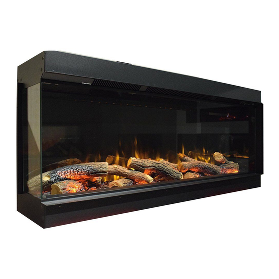
- Page 1 Best of British fires, fireplaces & stoves iRange Electric Fire Model: i750e/i1000e/i1250e/i1500e/i1800e/i2200e Please read the instructions carefully before installation or use and keep for future reference.
-
Page 3: Table Of Contents
CONTENTS ………………………………………………… Important Safety Information ……………………………………………………… Technical Specifications …………………………………………………………… Parts And Hardware ………………………………………………………… Appliance Dimensions ……………………………………………………… Installation Instructions ………………………………………………………… Operating Instructions …………………………………………………… Manual Control Panel ………………………………………………………… Remote Control ……………………………………………………………… APP Control …………………………………………………………………… Maintenance ………………………………………………………………… Service Parts list …………………………………………………………………………… Others... -
Page 4: Important Safety Information
1. IMPORTANT SAFETY INFORMATION 1.1 Read all of the instructions carefully before using the appliance. 1.2 For indoor use only. This appliance is not suitable for use outside the house and only suitable for well insulated spaces or occasional use. 1.3 Do not use this appliance in the immediate surroundings of a bath, a shower or a swimming pool. -
Page 5: Technical Specifications
1.15 Some parts of this product can become very hot and cause burns. Particular attention has to be given where children and vulnerable people are present. 1.16 Do not use this appliance in small rooms when they are occupied by persons not capable of leaving the room on their own, unless constant supervision is provided. -
Page 6: Parts And Hardware
Type of Heat Output / Room Temperature Control Single stage heat output and no room temperature control Two or more manual stages, no room temperature control With mechanic thermostat room temperature control With electronic room temperature control Electronic room temperature control plus day timer Electronic room temperature control plus week timer Other Control Options Room temperature control, with presence detection... - Page 7 Firebox (1pc) ST4*8 Screw (5pcs) ST5*40 Screw (18pcs) Power Cord Bracket (1pc) (Installer must fit before ST4*40 Screw (4pcs) Wall Plug (18pcs) leaving appliance) Lower Brackets (2pcs) (To be used when the wall Edging Strips (2pcs) Edging Strips (2pcs) haning bracket(J) is used) Wall hanging bracket is attached on firebox (1pc) Sucker...
-
Page 8: Appliance Dimensions
Vermiculate (1set) Remote (1pc) AAA Battery (2pcs) Instruction Manual (1pc) Simplified Instruction (1pc) 4. APPLIANCE DIMENSIONS Unit:mm Model i750e 1030 i1250e 1000 1030 i1250e 1250 1280... -
Page 9: Installation Instructions
Model i1500e 1500 1530 i1800e 1800 1830 i2200e 2200 2230 5. INSTALLATION INSTRUCTIONS 5.1 PREPARATION BEFORE INSTALLATION Tools Required A screwdriver, a spirit level and drill will be needed. Locate the Appliance Your new electric fireplace may be installed virtually anywhere in your home. - Page 10 Connect the Mood Light Cable The interface of the mood light cable is on the rear of the appliance, near the position of the power cord. Please also check the function after connecting the mood light. N o t e : c o m p a t i b l e m o o d l i g h t i n g d e v i c e s a r e a v a i l a b l e f r o m Charlton&Jenrick Ltd., Other brands may not be suitable and void the warranty.
- Page 11 Remove the front glass panel Remove the 2c/s screws and remove the glass retaining strip as shown Ÿ below. Use a suction cup(s) provided to support the middle of the glass panel and Ÿ lift the panel upwards and pull it forwards at its lower edge. Carefully lift glass away as shown below.
- Page 12 5.2 Installation The following is only given as a general guide because it can be installed in so many ways. Provided you ensure electric connections are safely made in accordance with the codes,various materials can be used for the framework and cladding. But consideration should be made to soften the internal surface of any cladding to minimise that amplification of noise.
- Page 13 Cladding the framework. Note:Hard surfaces can amplify sound. Consider Ÿ adding some underlay or similar to the inside surface of the cladding . WALL MOUNTED Remove the wall bracket from the rear of the appliance, and place it Ÿ horizontally against the wall where you would like to install the appliance. Mark the holes for screws, drill holes on the marks, insert wall plugs and fix the bracket to the wall by ST5x40 screws .
-
Page 14: Operating Instructions
Lift the appliance up and attach to the wall mounting bracket. Mark the hole Ÿ position of the lower fixing bracket, take the appliance down, drill holes on the marks and insert wall plug into it. Attach the appliance again on the bracket, secure the appliance to the wall Ÿ... -
Page 15: Manual Control Panel
6a. MANUAL CONTROL STAND-BY WiFi FLAME HEATER MANUAL SWITCH Press “ ” to turn on the appliance ;Press “ ” to turn off it. STAND-BY Press to turn on/off flame、downlight、and fuel bed effect . FLAME Press repeatedly to cycle through 6 fire preset modes and 3 user defined presets if programmed. -
Page 16: Remote Control
6b. REMOTE CONTROLS TEMPERATURE SENSOR DISPLAY MY FLAME STANDBY FLAME CRACKLE CHOICE FUEL BED MOOD LIGHT HEATING TIMER Timer and Week Advance Timer Mode Battery Power Actual Room Temperature Heating Period Temperature Set NOTE: The remote control handset must be left in the same room as the appliance because it houses the thermostat that regulates heat output.Also, when using the APP, the remote must also be in same room and have batteries fitted and working to ensure accurate temperature... - Page 17 There are 3 preset slots allocated for the user to save personalised. Simply choose the flame colour and brightness level, the fuel bed colour and brightness level. Once you have selected your desired combination, press and hold the My flame button for 3 seconds until the LCD displays My Flame save to 7 Press ' or '...
- Page 18 This happens because the room temperature is at or above the temperature set on the remote control. Timer Mode NOTE: This setting is only for operating in normal mode. It allows the appliance to go into standby after a set period of time. Press to cycle through the settings from 0.5 hours to 10 hours, and then OFF.
-
Page 19: App Control
the appliance has been reset. Re-setting of the E.S. Control proceeds is as follows: 1. Switch off the appliance (Manual switch) and leave it of for approximately 10-15 minutes. 2. Remove any obstruction to the fan heater outlet or fan blades etc. Make sure that the power supply is disconnected with the plug socket outlet while doing this. -
Page 20: Maintenance
Operation instruction and Video APP Download 7. MAINTENANCE WARNING: Before any maintenance or cleaning of the exterior of the appliance, the unit should be disconnected from the power supply remove supply plug from power socket or turn off and remove fuse from fused spur, wait until the appliance is cool. -
Page 21: Service Parts List
8. SERVICE PARTS LIST... -
Page 24: Others
9. OTHERS Environment Meaning of crossed –out wheeled dustbin: Electrical appliances should not be disposed as unsorted municipal waste. Separate collection facilities should be used in the disposal of electrical appliances. Contact your local government for the information about the available collection systems. - Page 25 Charlton & Jenrick Ltd Unit D, Stafford Park 2, Telford, Shropshire, TF3 3AR Tel: +44 1952 200 444 Fax :+44 1952 200 480 www.charltonandjenrick.co.uk...
Need help?
Do you have a question about the iRange i750e and is the answer not in the manual?
Questions and answers