Table of Contents
Advertisement
Owner's Manual
INCLUDES
User, Maintenance, Service, and Installation
Instructions
FOCUS 18 HE
Keep this booklet for service log and future reference
IMPORTANT
This appliance is guaranteed for 12 months subject to conditions. The 5 year extended parts
warranty will only be valid if the annual service recommended in this manual has been
completed and appliance has been registered online.
For use in Great Britain and Ireland.
Literature NO 5558 (ISS 7)
Advertisement
Table of Contents

Related Manuals for Charlton & Jenrick PARAGON FOCUS 18 HE


Summary of Contents for Charlton & Jenrick PARAGON FOCUS 18 HE
- Page 1 Owner’s Manual INCLUDES User, Maintenance, Service, and Installation Instructions FOCUS 18 HE Keep this booklet for service log and future reference IMPORTANT This appliance is guaranteed for 12 months subject to conditions. The 5 year extended parts warranty will only be valid if the annual service recommended in this manual has been completed and appliance has been registered online.
-
Page 2: Table Of Contents
Contents EXTENDED FIVE EXTENDED FIVE YEAR PARTS WARRANTY ....2 YEAR PARTS Benchmark Scheme ............. 3 WARRANTY SECTION ONE Introduction (user instructions) ..5 SECTION TWO Operating the Appliance (user In order to validate your extended 5 years parts instructions) ..............7 warranty please read the Benchmark Scheme on the opposite page and ensure your installer has filled in the SECTION THREE Cleaning (user instructions) .... -
Page 3: Benchmark Scheme
Benchmark Scheme Charlton and Jenrick Ltd is a licensed member of the Benchmark Scheme which aims to improve the standards of installation and commissioning of domestic heating and hot water systems in the UK and to encourage regular servicing to optimise safety, efficiency and performance. Benchmark is managed and promoted by the Heating and Hotwater Industry Council. - Page 4 Important For future reference we suggest you record the following details here, and keep the receipt as proof of purchase. This information may be asked for when you contact the helpdesk. MODEL: FOCUS 18 HE Serial No. This information can be found on the label attached to the packaging and on the data badge, which is located on the base of the appliance behind the control cover.
-
Page 5: Section One Introduction (User Instructions)
Introduction The PARAGON FOCUS 18 HE as been designed and tested for use in GB (Great Britain) and IE (Ireland). The PARAGON FOCUS 18 HE incorporates a single gas control, which selects ignition pilot, and main burner low and high settings. -
Page 6: Important Information
Important Information The appliance is for use on Natural Gas (G20 @ 20mbar) The chimney or flue (unless new or previously used with a gas appliance) shall be swept before installation if it has been used for solid fuel. ... -
Page 7: Section Two Operating The Appliance (User Instructions)
SECTION TWO Operating the Appliance (user instructions) The full lighting procedure is as follows: - 1. To gain access to the Control Knob remove the ash pan cover. 2. Push knob in as far as possible on gas control. 3. Turn knob anti-clockwise until a click is heard. The knob will stop at the position marked and a spark should be seen at the tip of the ignition probe. -
Page 8: Section Three Cleaning (User Instructions)
SECTION THREE Cleaning (user instructions) Warning: - Before you clean any part of the appliance ensures that the appliance is turned off and cold. Cleaning: Trim, Fret Or Fascia Abrasive or chemical cleaner should never be used. Cleaning: Black Painted Surfaces ... -
Page 9: Section Four Fuel Bed Cleaning And Layout (User Instructions)
Glass Cleaning From time to time it will be necessary to clean the glass panel of your Heat Machine fire. We recommend you use a Ceramic hob cleaner these are available for all leading super markets: - i.e. ASDA, TESCO, SAINSBURY’S Etc. Brands of hob cleaning we have tested and found suitable are - HOB BRITE &... - Page 10 Coal Fuel Bed Layout Locate the Rear Matrix on the burner ensuring that the front edge is against the back of the burner slot and not on top of it. Place the LH and RH Front Matrix in the channel at the front of the burner tray.
- Page 11 Lay another row of loose coals as shown. Lay another row of loose coals as shown and refit glass panel, www.charltonandjenrick.co.uk LT5558 (ISS 7)
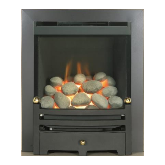
- Page 12 * Before fitting the pebble set loosen the burner securing screws and make sure that burner is pushed to the right side of the burner tray. This will ensure maximum aeration to the burner and reduce discolouration. Pebble Fuel Bed Layout (Refer to warnings at the beginning of this section.) ...
- Page 13 Lay another row of Pebble as shown. Lay another row of Pebbles as shown. www.charltonandjenrick.co.uk LT5558 (ISS 7)
-
Page 14: Section Five General Points (User Instructions)
SECTION FIVE General Points (user instructions) Like all appliances incorporating an aerated burner a low frequency noise may be heard, particularly on the low setting, this is quite normal and does not affect the operation of the appliance. It is advised that a competent person service the Paragon Focus HE fire annually. The fire is more likely to provide trouble-free operation. -
Page 15: Section Six Appliance Data (Installation Instructions)
SECTION SIX Appliance Data (installation instructions) NATURAL GAS Gas Type: CATEGORY I 2 H Gas Pressure: 20 mbar +/- 1.0mbar Pressure Test Point Location: Gas inlet elbow Gas Input: 5.7 kW Gross (Max.) 3.0 kW Gross (Min.) Injectors: Mk 365 Oxy pilot: 9044 Gas Connection:... -
Page 16: Section Seven Regulations And Warnings (Installation Instructions)
SECTION SEVEN Regulations and Warnings (Installation instructions) This appliance must only be installed in Great Britain or Ireland. The appliance is suitable for use on natural gas and propane GB (Great Britain) This fire does not normally require purpose build ventilation. ... -
Page 17: Section Eight Siting The Appliance (Installation Instructions)
SECTION EIGHT Siting the Appliance (installation instructions) CLASS ONE That is a conventional brick or stone chimney as used for a solid fuel appliance with an effective cross-sectional dimension of 225 x 225 mm (9” x 9”) or a lined flue with a minimum diameter of 125mm (5”). The chimney must have a minimum effective height of at least 3 metres. - Page 18 FIREPLACE OPENING 455-500mm TRIM / FACSIA DIMENSION ARE SPECIFIED IN THE APPLIANCE DATE SECTION. This area behind the trim/fascia must be clear of combustible material and be flat to accommodate the 560-580mm seal. When installing the standard four sided trim option this area at the base of the opening must be clear of combustible material and be flat to accommodate the seal.
- Page 19 Heath or Plinth Mounted When fire Hole In Wall fitted with STANDARD THREE SIDED (No Plinth) TRIM When fire fitted with STANDARD FOUR SIDED TRIM Heath / Plinth Size Width 505mm (Minimum Dimensions) Depth 100mm 50mm ‘X’ Ht from floor to base of 50mm 150mm opening.
-
Page 20: Section Nine To Install The Appliance (Installation Instructions)
Clearance to Shelf Minimum clearance from hearth or base of opening to underside of combustible shelf should be 780mm provided the shelf depth is 100mm (4”). This gives a minimum clearance above the appliance of 170mm. For a shelf of 150mm (6”) the minimum height above the hearth or base of opening must be 880mm. - Page 21 GAS SUPPLY ROUTING Use rigid or semi – rigid tube to connect the supply. Determine the gas supply pipe route to the appliance before installing the fire. STANDARD TRIM & FRET This may be from the front of the unit, either from the left or from the right hand, or it can be a concealed fitting from the rear of the appliance.
- Page 22 GLASS PANEL REMOVAL Refer to section 3 CONNECTING THE GAS SUPPLY For a concealed connection: - Remove the two fixing studs retaining the control cover and slide the bracket clear of the fixing studs. Remove the burner assembly by undoing the fixing screws two in front control fascia and two at the rear of burner plate.
-
Page 23: Section Ten Checking Operation Of Fire (Installation Instructions)
Method 2 (CABLE FIXING SYSTEM) Using a No 14 masonry bit drill two holes in the rear wall within the range shown, fit rawl plugs provided and screw eyebolts securely into plugs. Remove paper back from length of seal around the rear flange of the fire. NOTE: -The seal must be positioned to ensure an airtight seal when the appliance is fitted. - Page 24 LAY FUEL BED Important: - Refer to the Health & Safety Notice located on page 3 of this booklet before laying or replacing any refractory material. In the event of replacing fuel bed components please use only the specified number of components as illustrated. Only use fuel bed component provided for this appliance.
-
Page 25: Section Eleven Maintenance (Maintenance Instructions)
FIT STANDARD FIRE TRIM , FRET & FASCIA Fit the fire with the magnetic strips placed on the vertical side flange of the box. Avoid placing magnets along the top section of the trim. For four-sided trim fitting see instructions supplied with trim. ... - Page 26 TO REMOVE THE BURNER TRAY Turn off the gas supply by the isolating cock. Remove the fret, canopy, trim plus bracket, glass panel. Remove the loose fuel bed components. Undo the four burner tray fixing screws. Pull carefully forward and remove. ...
- Page 27 www.charltonandjenrick.co.uk LT5558 (ISS 7)
- Page 28 LT5558 (ISS 7)
- Page 29 Register your appliance online today to active your warranty www.charltonandjenrick.co.uk LT5558 (ISS 7)
-
Page 30: Gas Fire Commissioning Checklist
GAS FIRE COMMISSIONING CHECKLIST This Commissioning Checklist is to be completed in full by the competent person who commissioned the gas fire as a means of demonstrating compliance with the appropriate Building Regulations and then handed to the customer to keep for future reference. -
Page 31: Service Record
SERVICE RECORD It is essential that your gas fire is serviced regularly and that the appropriate Service Interval Record is completed. Service Provider Before completing the appropriate Service Record below, please ensure you have carried out the service as described in the manufacturer’s instructions. - Page 32 Product Serial No A-0194 ID Label Prefix (NG) Burner Tray / Box Assembly Restrictor Elbow (2189) Linings (Side, rear and top) Glass Panel Focus He 18 Coal Set (Part No 5554) Canopy & Fret Plate Sealing (4904) Wire Fixing Kit (A-0474) Magnet (4 X Segment 3048) 7mm Spinner (5435) Owners Book...
Need help?
Do you have a question about the PARAGON FOCUS 18 HE and is the answer not in the manual?
Questions and answers