Deif AGC 150 Operator's Manual
Generator marine stand-alone
Hide thumbs
Also See for AGC 150:
- Operator's manual (38 pages) ,
- Manual (28 pages) ,
- Installation instructions manual (22 pages)
Table of Contents
Advertisement
Quick Links
Advertisement
Table of Contents

Related Manuals for Deif AGC 150


Summary of Contents for Deif AGC 150
- Page 1 AGC 150 Generator marine stand-alone Operator's manual...
-
Page 2: Table Of Contents
......................................1.2 About the operator's manual ....................................... 1.3 Warnings and safety ..........................................1.4 Legal information ............................................2. About the AGC 150 Stand-alone marine 2.1 Stand-alone (island mode) ........................................2.1.1 Display, buttons and LEDs ......................................2.2 Emergency genset ............................................ 2.2.1 Display, buttons and LEDs ...................................... -
Page 3: Introduction
1. Introduction Symbols for hazard statements DANGER! This shows dangerous situations. If the guidelines are not followed, these situations will result in death, serious personal injury, and equipment damage or destruction. WARNING This shows potentially dangerous situations. If the guidelines are not followed, these situations could result in death, serious personal injury, and equipment damage or destruction. -
Page 4: Warnings And Safety
Legal information Third party equipment DEIF takes no responsibility for the installation or operation of any third party equipment, including the genset. Contact the genset company if you have any doubt about how to install or operate the genset. Warranty... -
Page 5: About The Agc 150 Stand-Alone Marine
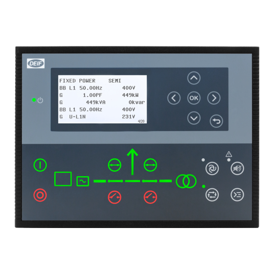
Stand-alone (island mode) Stand-alone (island mode operation) is typically used in power plants that are isolated from other power generation systems. NOTE For the AGC 150 Stand-alone controller, you can disable breaker control. 2.1.1 Display, buttons and LEDs Name Function Green: The controller power is ON. -
Page 6: Emergency Genset
Name Function Remote equipment (digital inputs, Modbus commands, AOP-2 commands) controls the AGC Remote mode 150. Silence horn Turns off an alarm horn (if configured) and enters the Alarm menu. Shortcut menu Access the Jump menu, Mode selection, Test, Lamp test The operator can use the display unit push buttons to start, stop, connect or disconnect the Local mode genset. -
Page 7: Display, Buttons And Leds
Turns off an alarm horn (if configured) and enters the Alarm menu. Shortcut menu Access the Jump menu, Mode selection, Test, Lamp test Remote equipment (digital inputs, Modbus commands, AOP-2 commands) controls the AGC 150. Semi-auto mode The operator can also use the display unit push buttons. -
Page 8: Display Settings
Name Function Green: There is running feedback. Engine Green flashing: The engine is getting ready. Red: The engine is not running, or there is no running feedback. Stop Stops the genset if Local or Semi-auto is selected. Start Starts the genset if Local or Semi-auto is selected. Green: The supply voltage and frequency are OK. -
Page 9: Running Modes
Standard The control buttons and LEDs are shown. If you stop the genset, the engine/generator symbols are not shown. Standard with genset The control buttons and LEDs are shown. If you the stop the genset, the engine/generator symbols are shown in red. Guided Active control buttons and LEDs are shown inactive are not shown. -
Page 10: Menus
3. Menus Menu structure The controller has two menu systems, which can be used without password entry: • The View menu system: Shows the operating status and values. The system has 20 configurable windows, that can be entered with the arrow buttons. •... -
Page 11: Menu Numbers
3.2.1 Menu numbers Each parameter has a menu number. You can find the number in the upper right corner on the display screen. You can also find the menu number with the utility software: 1. Select Parameters from the toolbar on the left. 2. -
Page 12: View Menu
View menu The view menu is shown when the controller is turned on, and you can see the operating status and values. The event and alarms list will also be shown if an alarm is on. 1. Operating status 2. Values and information 3. -
Page 13: Display Text
Line View 6 View 7 View 8 View 9 View 10 GOV and AVR EIC T. Oil output Ramp down/up EIC Regeneration info EIC T. Fuel setpoint Line View 11 View 12 View 13 View 14 View 15 P GTot and P % G Angle L1L2 0deg P 0kW 0% P available 0kW... -
Page 14: Status Texts
Display text You can select five of the display texts for each display view. Status texts Status text Condition ACCESS LOCK The configurable input is activated, and the operator tries to activate one of the blocked keys. Aux. test ##.#V ####s The battery test is activated. -
Page 15: Service View
Status text Condition RUN COIL ON Run coil is active during the start sequence. SHUTDOWN OVERRIDE The configurable input is active. SIMPLE TEST ###.#min Test mode is activated and test timer counting down. START DG(s) IN ###s The start genset set point has been exceeded. The genset will start when the timer expires. START PREPARE The start prepare relay is activated. -
Page 16: Engine Shortcuts
Engine shortcuts 3.6.1 PID configuration You can use the engine shortcuts menu to configure the PID set points. On the controller 1. From the view menu, push the Shortcut button to see the menu. 2. Use the Up and Down buttons to go to Engine shortcuts menu, and push the button. -
Page 17: Exhaust After-Treatment (Tier 4/Stage V)
3. Select Force Regeneration. 4. Select Inhibit or Force. Exhaust after-treatment (Tier 4/Stage V) AGC 150 meets the Tier 4 (Final)/Stage V requirements. The user can use the display to monitor (and control) both the engine, and the exhaust after-treatment system. After-treatment page... - Page 18 Referent Symbol Description Engine emission system failure level Emission failure or malfunction, with the severity. Diesel Particle Filter (DPF) level Regeneration needed, with the severity. DEF level warning Low DEF level. DEF shutdown DEF problem stops normal operation. Mid-level inducement. DEF level inducement Severe inducement.
- Page 19 Engine dashboard Referent Symbol Description Water in fuel There is water in the fuel. Engine interface status An engine warning. Page name Controller status Engine interface status An engine shutdown. Engine interface status An engine malfunction. Cold start The engine is cold. High engine coolant temperature The engine coolant temperature is high.
- Page 20 Referent Symbol Description Oil change The engine needs an oil change. High engine oil temperature The engine oil temperature is high. NOTE Grey symbols show that communication is available for the referent. An engine type might not support all of the referents.
-
Page 21: Alarm Handling And Log List
4. Alarm handling and log list Alarm handling If the function Alarm Jump is on, the controller will automatically show the alarm list on the display screen when an alarm occurs. Service View > Display > Alarm Jump Parameter Text Range Default 9157... -
Page 22: Logs Menu
Logs menu These are the log sub-menus: 1. Event log: Shows up to 500 events. 2. Alarm log: Shows up to 500 alarms. Only the latest 100 alarms are shown on the display unit, while the remaining alarms are shown in the utility software. 3.
Need help?
Do you have a question about the AGC 150 and is the answer not in the manual?
Questions and answers