
Subscribe to Our Youtube Channel
Related Manuals for Fisher & Paykel customer care HC60DCXB 1


Summary of Contents for Fisher & Paykel customer care HC60DCXB 1
- Page 1 Service Manual Rangehood Models: HC60DCXB 1 HC90DCXB 1 HC120DCXB 1 Product Codes: 89369 80701 89361 80702 89362 590125...
- Page 2 590125 - July 2010 PRODUCTS Brand: Fisher & Paykel Voltage: 220–240v 50Hz Models: Model Description Product Code - Market HC60DCXB1 Brushed Stainless Steel 60cm Wide 89368 – GB 80701 – AA HC90DCXB1 Brushed Stainless Steel 90cm Wide 89361 – GB 80702 –...
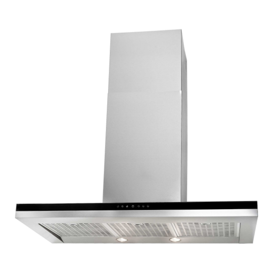
- Page 3 The specifications and servicing procedures outlined in this manual are subject to change without notice. The latest version is indicated by the reprint date and replaces any earlier editions. GUIDE TO USING THIS MANUAL The model covered by this manual is listed on the front cover. The front cover picture shows the type of product and may not necessarily be an exact image of the model covered by the manual.
-
Page 4: Table Of Contents
590125 CONTENTS HEALTH & SAFETY ......................5 SPECIFICATIONS .........................6 Product Dimensions......................6 Product Weight ........................6 Electrical Ratings .......................6 Noise Ratings (dba) ......................6 Maximum Air Flow (m3/Hr) ....................7 Serial Number........................7 Model Code Convention ......................7 Filters ............................8 Replacing Aluminium Filters....................8 Carbon Filter........................8 Recirculation........................8 Operation ..........................9 Five-Button Control Panel....................9 Using the Automatic Timer....................9 Service Procedures......................10... -
Page 5: Health & Safety
590125 HEALTH & SAFETY When servicing the Range Hood, Health & Safety issues must be considered at all times. Specific safety issues are listed below with the appropriate icon. Electrical Safety Ensure the mains power has been disconnected before servicing the Appliance. -
Page 6: Specifications
590125 SPECIFICATIONS Product Dimensions Product Weight HC60DCXB1 13.1 Kg HC90DCXB1 14.8 Kg HC120DCXB1 28 Kg Electrical Ratings 220 – 240V 50Hz 370W Noise Ratings (dba) Speed 1 Speed 2 Speed 3... -
Page 7: Maximum Air Flow (M3/Hr)
590125 Maximum Air Flow (m3/Hr) Speed 1 Speed 2 Speed 3 Serial Number This is located underneath the Aluminium Filters Model Code Convention... -
Page 8: Filters
590125 Filters Replacing Aluminium Filters • Depending on use, and at least once a month, the aluminium grease filters should be removed and cleaned in a dishwasher or with hot soapy water. If washed in a dishwasher, the filters should be placed in an upright position to prevent food from falling on them. -
Page 9: Operation
590125 Operation Five-Button Control Panel Filter cleaning alert indicator Activates to alert of the need to clean filters and deactivated with a single press Timer button The fan will operate for 15 minutes before automatically turning off Light button Turns the lights ON and OFF. Press and hold button to adjust the level of light. Power ON/OFF Fan speed buttons (1st, 2nd and 3rd speed) Using the Automatic Timer... -
Page 10: Service Procedures
590125 Service Procedures Removing Inner Panel • Disconnect the mains supply to Rangehood • Remove the aluminium filter • Remove the 12 screws (figure 1) Figure 1 • Lift inner panel off (figure 2) • Reassemble in reverse order Figure 2 Replacing the Halogen Lamps •... -
Page 11: Removing The Touch Controller Pcb
590125 Removing the Touch Controller PCB • Disconnect the mains supply to Rangehood • Remove inner panel (refer section 7.1) • Remove the 2 screws holding the controller (figure 7) Figure 7 • Slide controller out (figure 8) figure 8 •... -
Page 12: Motor Removal And Replacement
590125 Motor Removal and Replacement • Disconnect the mains supply to Rangehood • Remove the chimney covers and remove Rangehood from wall • Remove the lamp holder brackets by removing the 3 screws per bracket on the rear of the motor housing (figure 12) Figure 12 •... -
Page 13: Motor Disassembly
590125 Motor Disassembly • Remove motor from housing (refer section 7.5) • Remove the three screws on the end cover (figure 16) Figure 16 • Lift motor from cover (figure 17) Figure 17 • Remove the fan blade by undoing the centre nut and slide the fan blade off the shaft (figure Figure 18 •... -
Page 14: Connection Box Components And Removal
590125 Connection Box Components and Removal Located on the side of the motor • To access the components in the connection box unscrew the 4 screws indicated in figure 21 and the cover will lift off • To remove the complete connection box unscrew the 2 screws indicated in figure 21 and the complete box will lift off Power Module... -
Page 15: Wire Diagram
590125 7.10 Wire Diagram... -
Page 16: Notes
590125 Notes...
Need help?
Do you have a question about the customer care HC60DCXB 1 and is the answer not in the manual?
Questions and answers