Otto Bock C-Brace Instructions For Use Manual
Hide thumbs
Also See for C-Brace:
- Instructions for use manual (88 pages) ,
- Instructions for use manual (72 pages) ,
- Instructions for use manual (60 pages)
Table of Contents
Advertisement
Available languages
Available languages
Quick Links
17T1=* C-Brace DTO
Gebrauchsanweisung (Fachpersonal) ....................................................................
3
Instructions for use (qualified personnel) ................................................................. 33
Руководство по применению (Квалифицированный персонал) ............................... 63
Advertisement
Chapters
Table of Contents

Related Manuals for Otto Bock C-Brace


Summary of Contents for Otto Bock C-Brace
- Page 1 17T1=* C-Brace DTO Gebrauchsanweisung (Fachpersonal) ..............Instructions for use (qualified personnel) ..............33 Руководство по применению (Квалифицированный персонал) ....... 63...
- Page 2 17T1=* C-Brace DTO...
-
Page 3: Table Of Contents
Anlegen ............................. Ablegen ............................. Reinigung ................................Desinfektion ..............................Entsorgung ................................ Rechtliche Hinweise ............................10.1 Haftung ............................. 10.2 CE-Konformität ........................... Anhänge ................................11.1 Angewandte Symbole .......................... 11.2 Technische Daten .......................... C-Brace DTO – Protokoll Anwendertest (Kopiervorlage) ................17T1=* C-Brace DTO... -
Page 4: Vorwort
Gesundheitszustands, dem Hersteller und der zuständigen Behörde Ihres Landes. ► Bewahren Sie dieses Dokument auf. Die C-Brace Diagnostische Testorthese 17T1=* wird im Folgenden nur noch DTO, Produkt oder Orthese genannt. Diese Gebrauchsanweisung gibt Ihnen wichtige Informationen zur Verwendung, Einstellung und Handhabung des Produkts. -
Page 5: Bestimmungsgemäße Verwendung
Die Indikation wird vom Arzt gestellt. 4.5 Kontraindikationen • Beugekontraktur im Knie- und/oder Hüftgelenk über 10° • Varus Fehlstellung über 10° oder Valgus Fehlstellung über 10° • Starke Spastizität • Körpergewicht über 125 kg / 275 lbs 17T1=* C-Brace DTO... -
Page 6: Qualifikation Des Orthopädie-Technikers
► Stellen Sie das korrekte Anlegen und den korrekten Sitz des Produkts sicher. ► Verwenden Sie das Produkt bei Passformproblemen nicht weiter. VORSICHT Kontakt mit Hitze, Glut oder Feuer Verletzungsgefahr (z. B. Verbrennungen) und Gefahr von Produktschäden ► Halten Sie das Produkt von offenem Feuer, Glut oder anderen Hitzequellen fern. 17T1=* C-Brace DTO... -
Page 7: Gebrauch
► Halten Sie zu einem Herzschrittmacher mindestens 12 cm Sicherheitsabstand ein. Vor der erstmaligen Verwendung des Produkts, muss die Handhabung und der Umgang erlernt werden. Das An- und Ausziehen, das Hinsetzen und Aufstehen sowie die Fortbewegung müssen trainiert werden. 17T1=* C-Brace DTO... -
Page 8: Anpassen
Den Oberschenkelumfang des Patienten messen und die geeignete Oberschenkelbeinhülse nach Tabelle auswählen. Den Wadenumfang des Patienten messen und die ge eignete Unterschenkelbeinhülse nach Tabelle auswäh len. Zur Bestimmung der Länge des Basisrohrs die Unter schenkellänge von Kniespalt bis Boden messen. 17T1=* C-Brace DTO... -
Page 9: Beinhülse An Der Verstelleinheit Wechseln
Richtung die Einheit abgezogen wird. Oberschenkeleinheit = nach vorne abziehen Unterschenkeleinheit = nach hinten abziehen Die vordere Mutter mit einem Torxschlüssel T 25 an der oberen Verstelleinheit lösen. Die Mutter abnehmen. Die Oberschenkelhülse mit der Verstelleinheit von der Orthese nach vorne abziehen. 17T1=* C-Brace DTO... - Page 10 Die Verstelleinheit mit der Oberschenkelhülse auf die Rahmenkonstruktion aufsetzen. Dabei die magnetischen Zylinderstifte in die Hülsenhal terung einführen und gleichzeitig am Langloch der Ver stelleinheit ausrichten. Die Mutter aufsetzen und mit dem Torxschlüssel T 25 mit Anzugsmoment 4 Nm anziehen. 17T1=* C-Brace DTO...
-
Page 11: Patientenmaße Auf Dto Übertragen
Die Schraube des Unterschenkel-Basisrohrs mit einem Torxschlüssel T 25 lockern. Das Längenmaß "Kniespalt - Boden" auf die Orthese übertragen und auf die Unterschenkellänge des Pati enten einstellen. Die Schraube mit Torxschlüssel T 25 und Anzugsmo ment 6 Nm anziehen. 17T1=* C-Brace DTO... - Page 12 6 Nm anziehen. Anschließend das Basisrohr in das Trägerrohr der Or these einschieben. Das Längenmaß "Kniespalt - Boden" auf die Orthese übertragen und auf die Unterschenkellänge des Pati enten einstellen. Die Schraube am Trägerrohr mit An zugsmoment 6 Nm anziehen. 17T1=* C-Brace DTO...
-
Page 13: Ausgleichsschuh Anlegen
Patienten anpassen. Die folgenden Bilder zeigen das Anlegen des Unterschenkelpolsters. Das Unterschenkelpolster verfügt über eine umklappbare Lasche. Die Lasche dient zum Schutz vor einer Kom pression durch die Unterschenkelhülse und verhindert das Herausrutschen des Polsters aus der Hülse. 17T1=* C-Brace DTO... - Page 14 Die folgenden Bilder zeigen das Anlegen des Oberschenkelpolsters. INFORMATION: Das Oberschenkelpolster verfügt zusätzlich über zwei Klettpunkte, diese dienen zur Fixierung des Oberschenkelpolsters an der Ober schenkelhülse. Das Polster, mit den beiden Klettpunkten nach oben zeigend, am Oberschenkel anlegen. Das Oberschenkelpolster am Klettverschluss verschlie ßen. 17T1=* C-Brace DTO...
-
Page 15: Produkt Anlegen And Patientenspezifisch Anpassen
= geöffnet unten = geschlossen Das im Gelenk gestreckte Produkt dem Patienten anle gen. Zunächst die Ferse und dann den Fuß im Fußteil plat zieren. Die Unterschenkelhülse über dem optional verwende ten Unterschenkelpolster oder über dem Unterschenkel platzieren. 17T1=* C-Brace DTO... - Page 16 Das Fußteil einer bestehenden Orthese abschrauben und mitverwen den, dabei den Höhenausgleich berücksichtigen. Den Fersenspanngurt des Fußteils festziehen oder ent spannen, um so die Stellung des Fußes im Fußteil in A- P Richtung anzupassen. 17T1=* C-Brace DTO...
- Page 17 Gebrauch Optional: Zur besseren Fixierung des Fußes im Fußteil lateral oder medial ein Polster einbringen. Die Verschlussgurte am Fußteil schließen. Überprüfen Sie die Position des Orthesenknöchelge lenks zum Knöchel des Patienten. 17T1=* C-Brace DTO...
- Page 18 Das Trägerrohr nach oben oder nach unten verschie ben, bis der anatomische Kompromissdrehpunkt er reicht ist. Bei Erreichen der patientenspezifischen Position die Verschraubung am Trägerrohr feststellen. Den Anzugs moment 6 Nm beachten. Den Kniebeugeausschnitt kontrollieren und durch Ver schieben der Verstelleinheit patientenspezifisch anpas sen. 17T1=* C-Brace DTO...
- Page 19 Torxschlüssel T 25 lösen. Die Unterschenkelhülse in AP-Richtung verschieben, bis der Laser auf den Kompromissdrehpunkt zeigt. Anschließend die beiden Schrauben am Klemmadapter der Verstelleinheit mit Torxschlüssel T 25 und mit An zugsmoment 4 Nm festziehen, dabei Richtungspfeile (↔ anterior/posterior) beachten. 17T1=* C-Brace DTO...
- Page 20 Voraussetzung: Der Spannverschluss der Unterschenkelhülse ist geöffnet. • Voraussetzung: Optional: Das Oberschenkelpolster ist angelegt. • Voraussetzung: Die Oberschenkelhülse ist an der Verstelleinheit befestigt. • • Voraussetzung: Die Spannverschlüsse der Oberschenkelhülse sind geöffnet. Voraussetzung: Das Produkt ist im Kniegelenk gebeugt. • 17T1=* C-Brace DTO...
- Page 21 Orthese verschraubt werden. Die beiden Klettpunkte des optional verwendeten Ober schenkelpolsters an der Oberschenkelhülse festkletten. Alle Schraubverbindungen der Verstelleinheiten überprüfen und im Sitzen anziehen. Die Einstellungen für das Kniegelenk 17KO=1* beach ten. Siehe Begleitdokumentation Gebrauchsanweisung 647G1337! 17T1=* C-Brace DTO...
- Page 22 Voraussetzung: Das Produkt ist am Bein des Patienten angelegt. • INFORMATION: Die sagittale Stellung (A-P) des Beines kann durch Verschieben der Beinhülsen mit der Verstelleinheit verändert werden. » Die Orthese ist gestreckt und das Bein ist gebeugt. 17T1=* C-Brace DTO...
- Page 23 Die Kniedrehpunkte stimmen nicht überein. Die Unterschenkelhülse nach anterior verschieben. Die Kniedrehpunkte stimmen überein. Die Oberschenkelhülse nach posterior verschieben. INFORMATION: Die Stellung des Beines kann durch Verschieben der Beinhülsen mit der Verstelleinheit in M-L Richtung optimiert werden. 17T1=* C-Brace DTO...
- Page 24 Anschließend die beiden Schrauben am Klemmadapter der Verstelleinheit mit einem Torxschlüssel T 25 mit An zugsmoment 4 Nm festziehen, dabei Richtungspfeile (↕ distal/proximal) beachten. Die beiden Schrauben am Klemmadapter der Verstel leinheit mit einem Torxschlüssel lösen, dabei die Rich tungspfeile (↔ anterior/posterior) beachten. 17T1=* C-Brace DTO...
- Page 25 Zum Kippen der Oberschenkelhülse die beiden Muttern an der Verstelleinheit lösen. Durch Kippen der Verstelleinheit die Oberschenkelhül se am Bein des Patienten ausrichten. Die beiden Muttern an der Verstelleinheit mit Anzugs moment 4 Nm anziehen. Die Position und den Sitz der Oberschenkelhülse prü fen. 17T1=* C-Brace DTO...
- Page 26 Das Ausgleichspolster von oben komplett einschieben. Unterschenkelmodul einstellen Für die Unterschenkel-Verstelleinheit die Arbeitsschritte analog zur Oberschenkel-Verstelleinheit durchführen. Die beiden Schrauben lösen und die Pfeilrichtung be achten. Die Verstelleinheit verschieben, dabei die individuellen Besonderheiten, die der Patient und sein Körper vorge ben, beachten. 17T1=* C-Brace DTO...
- Page 27 Im Bedarfsfall kann der Abstand der Verstelleinheit zwi schen Trägerrohr und Beinhülse angepasst werden. Die beiden seitlichen Muttern am Schlitten der Verstel leinheit mit einem Torxschlüssel T 25 lockern. Das Bild zeigt die horizontale Verschiebemöglichkeit in M-L Richtung. 17T1=* C-Brace DTO...
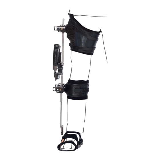
- Page 28 Die beiden seitlichen Muttern am Schlitten der Verstel leinheit mit einem Torxschlüssel T 25 und Anzugsmo ment 4 Nm festziehen. DTO angelegt und korrekt ausgerichtet Durch die M-L Justierung der Verstelleinheit ist die Beinachse gut ersichtlich. Optimale A-P Ausrichtung. 17T1=* C-Brace DTO...
-
Page 29: Anlegen
2) Das Produkt mit einem fusselfreien Tuch abtrocknen und an der Luft vollständig trocknen lassen. 8 Desinfektion • Vor Verwendung an einem anderen Anwender das Produkt mit einem farblosen, alkoholfreiem Desinfektions mittel reinigen. • Alle Teile des Produkts mit Desinfektionsmittel feucht abwischen. 17T1=* C-Brace DTO... -
Page 30: Entsorgung
Kennzeichen DTO für rechte Seite 17T1=R Gewicht DTO (ohne Gelenkeinheit) ca. 3,6 kg Maximales Patientengewicht 125 kg Lebensdauer des Produkts 6 Jahre Umgebungsbedingungen Lagerung und Transport in der Originalverpackung -25 °C bis +70 °C Lagerung und Transport ohne Verpackung -10 °C bis +40 °C nicht kondensierend 17T1=* C-Brace DTO... -
Page 31: C-Brace Dto - Protokoll Anwendertest (Kopiervorlage)
C-Brace DTO – Protokoll Anwendertest (Kopiervorlage) C-Brace DTO – Protokoll Anwendertest (Kopiervorlage) Datum:________________ Mitarbeiter: _________________________ Name: __________________________ Vorname:_____________________________ Alter:___________ männlich weiblich Diagnose: ______________________________________________________________________________ Testseite: rechts links Wichtigste Patientenziele: (Was verspricht er/sie sich von dem Produkt) 1. _______________________________________________________________________________ 2. _______________________________________________________________________________ Patient erfüllt das Ziel noch nicht Patient erfüllt das Ziel teilweise... - Page 32 17T1=* C-Brace DTO...
- Page 33 Cleaning ................................Disinfection ................................ Disposal ................................Legal information .............................. 10.1 Liability .............................. 10.2 CE conformity ............................. Appendices ................................ 11.1 Symbols Used ............................ 11.2 Technical data ............................ C-Brace DTO – user test protocol (template for copying) ................17T1=* C-Brace DTO...
-
Page 34: Foreword
► Please keep this document for your records. The 17T1=* C-Brace diagnostic trial orthosis is referred to simply as the DTO, product or orthosis below. These instructions for use provide you with important information on the use, adaptation and handling of the product. -
Page 35: Intended Use
The DTO is intended exclusively for orthotic fittings of the lower limbs and may only be used in combination with the 17KO1=* C-Brace knee joint. The knee joint is adjusted by qualified personnel using an adjustment app, sub ject to the 647G1337 instructions for use. -
Page 36: Qualification Of The O&P Professional
► Do not continue to use the product if there are problems with the correct fit. CAUTION Contact with heat, embers or fire Risk of injury (such as burns) and risk of product damage. ► Keep the product away from open flames, embers and other sources of heat. 17T1=* C-Brace DTO... -
Page 37: Use
► Maintain a safety distance of at least 12 cm from a pacemaker. Handling and use of the product must be learned before using it for the first time. Applying and removing, sitting down and standing up as well as walking must be practised. 17T1=* C-Brace DTO... -
Page 38: Adaptation
Measure the patient's calf circumference and choose the suitable lower leg sleeve according to the table. To determine the length of the base tube, measure the lower leg length from the MTP to the floor. 17T1=* C-Brace DTO... -
Page 39: Changing The Leg Sleeve On The Adjustment Unit
Lower leg unit = pull of backward Loosen the front nut on the upper adjustment unit with a T 25 Torx wrench. Remove the nut. Pull the thigh sleeve with the adjustment unit off the orthosis to the front. 17T1=* C-Brace DTO... - Page 40 In doing so, insert the magnetic cylinder pins into the sleeve holder and simultaneously align according to the slotted hole of the adjustment unit. Put on the nut and tighten it with a T 25 Torx wrench to a tightening torque of 4 Nm. 17T1=* C-Brace DTO...
-
Page 41: Transferring Patient Measurements To The Dto
Loosen the lower leg base tube screw with a T 25 Torx wrench. Transfer the "MTP-floor" length measurement to the orthosis and adjust to the patient's lower leg length. Use a T 25 Torx wrench to tighten the screw to a tight ening torque of 6 Nm. 17T1=* C-Brace DTO... - Page 42 Then insert the base tube into the holder tube of the orthosis. Transfer the "MTP-floor" length measurement to the orthosis and adjust to the patient's lower leg length. Tighten the screw on the holder tube to a tightening torque of 6 Nm. 17T1=* C-Brace DTO...
-
Page 43: Putting On The Compensating Shoe
The illustrations that follow show the application of the calf pad. There is a folding flap on the calf pad. This flap protects against compression by the lower leg sleeve and prevents the pad from sliding out of the sleeve. 17T1=* C-Brace DTO... - Page 44 INFORMATION: The thigh pad has two additional hook-and-loop patches to secure the thigh pad on the thigh sleeve. Apply the pad to the thigh with the two hook-and-loop patches facing up. Fasten the hook-and-loop closure on the thigh pad. 17T1=* C-Brace DTO...
-
Page 45: Product Application And Patient-Specific Adjustment
Apply the product, extended in the joint, to the patient. First position the heel and then the foot in the foot com ponent. Position the lower leg sleeve over the optional calf pad or over the lower leg. 17T1=* C-Brace DTO... - Page 46 Tighten or loosen the heel tension strap of the foot com ponent to adjust the position of the foot in the foot com ponent in the A-P direction. 17T1=* C-Brace DTO...
- Page 47 Optional: Install a lateral or medial pad for better fixa tion of the foot in the foot component. Fasten the closure straps on the foot component. Check the position of the orthosis ankle joint relative to the patient's ankle joint. 17T1=* C-Brace DTO...
- Page 48 When the patient-specific position is reached, tighten the screw connection on the holder tube. Observe the tightening torque of 6 Nm. Check the opening in the hollow of the knee and adjust it to the patient by shifting the adjustment unit. 17T1=* C-Brace DTO...
- Page 49 Then tighten the two screws on the clamp adapter of the adjustment unit with a T 25 Torx wrench to a tight ening torque of 4 Nm, taking note of the direction arrows (↔ anterior/posterior). 17T1=* C-Brace DTO...
- Page 50 Prerequisite: Optional: The thigh pad has been applied. • Prerequisite: The thigh sleeve has been mounted on the adjustment unit. • • Prerequisite: The clamp fasteners of the thigh sleeve are open. Prerequisite: The product is flexed in the knee joint. • 17T1=* C-Brace DTO...
- Page 51 Check all screw connections of the adjustment unit and tighten them in the sitting position. Note the settings for the 17KO=1* knee joint. See the accompanying documentation, 647G1337 instructions for use! 17T1=* C-Brace DTO...
- Page 52 Prerequisite: The product has been applied to the patient's leg. • INFORMATION: The sagittal position (A-P) of the leg can be adjusted by shifting the leg sleeves with the adjustment unit. The orthosis is extended and the leg is flexed. 17T1=* C-Brace DTO...
- Page 53 Shift the lower leg sleeve to anterior. The knee pivot points match. Shift the thigh sleeve to posterior. INFORMATION: The leg position can be optimised by shifting the leg sleeves in the M-L direction with the adjustment unit. 17T1=* C-Brace DTO...
- Page 54 T 25 Torx wrench to a tight ening torque of 4 Nm, taking note of the direction arrows (↕ distal/proximal). Loosen the two screws on the clamp adapter of the adjustment unit with a Torx wrench, taking note of the direction arrows (↔ anterior/posterior). 17T1=* C-Brace DTO...
- Page 55 Align the thigh sleeve on the patient's leg by tilting the adjustment unit. Tighten the two nuts on the adjustment unit to a tighten ing torque of 4 Nm. Check the position and fit of the thigh sleeve. 17T1=* C-Brace DTO...
- Page 56 Complete the process steps for the lower leg adjust ment unit similar to the thigh adjustment unit. Loosen the two screws and note the arrow direction. Shift the adjustment unit, taking note of the individual particularities of the patient and their body. 17T1=* C-Brace DTO...
- Page 57 Loosen the two lateral nuts on the carriage of the adjustment unit with a T 25 Torx wrench. The illustration shows the possible horizontal shift in the M-L direction. 17T1=* C-Brace DTO...
- Page 58 T 25 Torx wrench to a tightening torque of 4 Nm. DTO applied to the patient and correctly aligned Due to the M-L shifting of the adjustment unit, the leg axis is readily apparent. Optimum A-P alignment. 17T1=* C-Brace DTO...
-
Page 59: Application
Align the holder tube as close to perpendicular (90°) to the floor as possible. 6.2 Application Note the 647G1337 instructions for use of the 17KO1=* C-Brace knee joint. 1) Sit on the front edge of a chair. 2) Put the lining stocking onto the leg or use long trousers. -
Page 60: Legal Information
Reference number DTO for right side 17T1=R Weight DTO (without joint unit) approx. 3.6 kg Maximum patient weight 125 kg Product service life 6 years Ambient conditions Storage and transport in original packaging -25 °C to +70 °C Storage and transport without packaging -10 °C to +40 °C non-condensing 17T1=* C-Brace DTO... -
Page 61: C-Brace Dto - User Test Protocol (Template For Copying)
C-Brace DTO – user test protocol (template for copying) C-Brace DTO – user test protocol (template for copying) Date:________________ Employee: _________________________ Last name: __________________________ First name:_____________________________ Age:___________ male female Diagnosis: ______________________________________________________________________________ Test side: right left Key patient objectives: (what does the patient expect of the product) 1. - Page 62 17T1=* C-Brace DTO...
- Page 63 Дезинфекция ..............................Утилизация ............................... Правовые указания ............................10.1 Ответственность ..........................10.2 Соответствие стандартам ЕС ......................Приложения ..............................11.1 Применяемые символы ........................11.2 Технические характеристики ...................... C-Brace DTO – протокол тестирования ортеза пользователем (оригинал для копирования) ..17T1=* C-Brace DTO...
-
Page 64: Предисловие
► О каждом серьезном происшествии, связанном с изделием, в частности об ухудшении состояния здоро вья, сообщайте производителю и компетентным органам вашей страны. ► Храните данный документ. Диагностический тестовый ортез C-Brace 17T1=* далее упоминается как DTO, изделие или ортез. Данное руководство по применению содержит важную информацию по использованию, регулировке и обра щению с изделием. -
Page 65: Использование По Назначению
девании и снятии ортеза, а также сидении, стоянии, перемещении, и, в особенности, обучить его ходьбе на зад. 4.4 Показания • Односторонний или двусторонний парез ноги или вялый паралич Показания определяются врачом. 4.5 Противопоказания • Контрактура мышц-сгибателей в коленном и/или бедренном суставе более 10° • Варусная или вальгусная деформация более 10° 17T1=* C-Brace DTO... -
Page 66: Квалификация Техника-Протезиста
Неправильное или слишком плотное прилегание изделия к телу Возникновение явлений сдавливания, сужения кровеносных сосудов и сдавления нервов вследствие не правильного прилегания ► Проверьте правильность прилегания и посадки изделия. ► Не используйте изделие при возникновении проблем с посадкой. 17T1=* C-Brace DTO... - Page 67 ► Немедленно замените поврежденный лазер. ВНИМАНИЕ В изделии имеется магнит Воздействие на приборы и предметы или их повреждение вследствие воздействия сильного магнитного по ля ► Держите изделие на удалении от приборов и предметов, чувствительно реагирующих на воздействие магнитных полей. 17T1=* C-Brace DTO...
-
Page 68: Эксплуатация
36 - 49 Измерить объем бедра пациента и выбрать гильзу на бедро в соответствии с данными, приведенными в таблице. Измерить объем икроножной мышцы пациента и вы брать гильзу на голень в соответствии с данными, приведенными в таблице. 17T1=* C-Brace DTO... -
Page 69: Замена Гильзы На Нижнюю Конечность На Регулировочном Блоке
лировочном блоке указывает, которую из двух гаек необходимо удалить и в каком направле нии снимается блок. Блок бедра = снимается в направлении вперед Блок голени = снимается в направлении назад Открутить переднюю гайку ключом-звездочкой T 25 на переднем регулировочном блоке. Снять гайку. 17T1=* C-Brace DTO... - Page 70 главу "Точная настройка регулировочных блоков"). Затянуть винты до момента затяжки 4 Нм. Установить регулировочный блок с гильзой на бедро на рамочную конструкцию. Для этого ввести магнитные цилиндрические штифты в держатель гильзы и одновременно выполнить регу лировку в продольном пазу. 17T1=* C-Brace DTO...
-
Page 71: Перенос Размеров Пациента На Dto
вой трубки на голень: маленький (менее 47 см) и большой. Измерительная шкала на базовой трубке служит индикатором различной длины. Трубка одного размера предварительно смонти рована в ортезе, трубка другого размера входит в комплект поставки. Ослабить ключом-звездочкой T 25 винт базовой трубки голени. 17T1=* C-Brace DTO... - Page 72 При замене снять базовую трубку с несущей трубки ортеза. Ослабить оба винта на голеностопном узле ортеза с помощью ключа-звездочки T 25. Закрепить новую базовую трубку на голеностопном узле ортеза с помощью двух винтов и затянуть до мо мента затяжки 6 Нм. 17T1=* C-Brace DTO...
-
Page 73: Надевание Компенсаторного Ботинка
ке, начиная с пятки. По очереди закрыть все ремешки в последователь ности: на лодыжке > на подъеме стопы > на носке. В качестве опции: отрегулировать посадку обуви пациента в компенсаторном ботинке натяжением ре мешков или с помощью мягких подкладок. 17T1=* C-Brace DTO... -
Page 74: В Качестве Опции: Использование Мягких Подкладок
На следующих рисунках продемонстрировано наложение мягкой подкладки на бедро. ИНФОРМАЦИЯ: на подкладке на бедро имеют ся две дополнительные точки-липучки, которые служат для фиксирования подкладки на голень на гильзе на бедро. Наложить мягкую накладку на бедро, обе точки-ли пучки при этом должны быть обращены вверх. 17T1=* C-Brace DTO... -
Page 75: Наложение Изделия И Регулировка В Соответствии С Потребностями Пациента
закрыть ее движением вправо (см. на рисунке внизу). Следить за тем, чтобы все защелки были надеж но закрыты. Застежки натяжных ремешков: вверху = открыта внизу = закрыта Надеть изделие с разогнутым модулем на пациента. Разместить в блоке стопы вначале пятку, затем всю стопу. 17T1=* C-Brace DTO... - Page 76 вернуть накладку поверх гильзы на голень. Застегнуть фиксирующие ремни блока стопы. ИНФОРМАЦИЯ: можно использовать блок сто пы имеющегося ортеза. Отвинтить блок стопы имеющегося ортеза и подготовить к использо ванию, при этом обратить внимание на компен сацию по высоте. 17T1=* C-Brace DTO...
- Page 77 подгонки положения стопы в переднезаднем напра влении. В качестве опции: для лучшей фиксации стопы в блоке стопы в латеральном или медиальном положе нии следует использовать мягкую подкладку. Застегнуть фиксирующие ремни блока стопы. Проконтролировать положение голеностопного узла ортеза относительно щиколотки пациента. 17T1=* C-Brace DTO...
- Page 78 Сместить несущую трубку вверх или вниз до дости жения компромиссного центра вращения. При достижении индивидуальной позиции зафикси ровать резьбовое соединение на несущей трубке. Соблюдать момент затяжки 6 Нм. Проверить положение выемки для сгибания колена и выполнить регулировку под пациента путем смеще ния регулировочного блока. 17T1=* C-Brace DTO...
- Page 79 Сместить гильзу на голень в направлении A-P (пе реднезаднее направление), пока лазерный луч не укажет компромиссный центр вращения. Затем затянуть ключом-звездочкой T 25 оба винта на адаптере фиксатора регулировочного блока момен том затяжки 4 Нм, обращая при этом внимание на стрелки (↔ переднезаднее направление). 17T1=* C-Brace DTO...
- Page 80 Условие: застежка натяжного ремня гильзы на голень расстегнута. • Условие: опционально: мягкая накладка на бедро размещена в своем месте. • Условие: гильза бедра закреплена на регулировочном блоке. • • Условие: застежки натяжных ремешков гильзы на бедро расстегнуты. Условие: коленный узел изделия согнут. • 17T1=* C-Brace DTO...
- Page 81 Закрепить обе точки-липучки мягкой накладки на бе дро (если используется) на гильзе на бедро. Проконтролировать все резьбовые соединения регулировочных блоков и надеть изделия сидя. Обращать внимания на настройки коленного узла 17KO=1*. См. прилагаемую документацию — руководство по применению 647G1337! 17T1=* C-Brace DTO...
- Page 82 Условие: пациент стоит с поддержкой другого лица или надежно опирается на ходунки. • Условие: изделие надето на пациента. • ИНФОРМАЦИЯ: сагиттальное положение (A-P) нижней конечности можно изменить путем смеще ния гильз на нижнюю конечность с помощью регулировочного блока. » Ортез выпрямлен, и нога согнута. 17T1=* C-Brace DTO...
- Page 83 Центры вращения колена не совпадают. Сместить гильзу на голень кпереди. Точки вращения колена совпадают. Сместить гильзу на бедро кзади. ИНФОРМАЦИЯ: положение ноги можно оптимизировать путем смещения гильз на нижнюю конеч ность с помощью регулировочного блока в медиальном и латеральном направлении. 17T1=* C-Brace DTO...
- Page 84 адаптере фиксатора регулировочного блока до мо мента затяжки 4 Нм, при этом обращать внимание на стрелки (↕ дистально-проксимальное направление). Ослабить ключом-звездочкой оба винта на адаптере фиксатора регулировочного блока, при этом обра щать внимание на стрелки (↔ переднезаднее направление). 17T1=* C-Brace DTO...
- Page 85 Чтобы наклонить гильзу бедра, необходимо ослабить обе гайки на регулировочном блоке. Путем наклона регулировочного блока гильзу на бе дро можно отрегулировать по ноге пациента. Затянуть обе гайки регулировочного блока до мо мента затяжки 4 Нм. Проконтролировать позицию и посадку гильзы на бедро. 17T1=* C-Brace DTO...
- Page 86 В отношении регулировочного блока голени выпол нить такие же рабочие шаги, как и при манипуляции с регулировочным блоком бедра. Отвинтить оба винта, обращать внимание на стрелку. Сместить регулировочный узел, обращая внимание на индивидуальные особенности пациента и его те ла. 17T1=* C-Brace DTO...
- Page 87 стояния от регулировочного блока до несущей труб ки и гильзы нижней конечности. Ослабить обе боковые гайки на каретке регулиро вочного блока с помощью ключа-звездочки T 25. На рисунке представлена возможность горизонталь ного смещения в M-L (медиолатеральном) направле нии. 17T1=* C-Brace DTO...
- Page 88 ного блока с помощью ключа-звездочки T 25 до мо мента затяжки 4 Нм. Ортез DTO наложен и отрегулирован надлежащим образом Благодаря выверке регулировочного блока в M-L (медиолатеральном) направлении наглядно просма тривается ось нижней конечности. Оптимальная настройка в A-P (переднезаднем) на правлении. 17T1=* C-Brace DTO...
-
Page 89: Указания По Надеванию
2) Витерите изделие насухо с помощью безворсовой салфетки или оставьте для полного высыхания на воз духе. 8 Дезинфекция • Перед использованием другим пользователем очистить изделие бесцветным и не содержащим спирта дезинфицирующим средством. • Протереть все детали изделия влажной салфеткой с применением дезинфицирующего средства. 17T1=* C-Brace DTO... -
Page 90: Утилизация
ок. 3,6 кг Максимальный вес пациента 125 кг Срок службы изделия 6 лет Условия применения изделия Хранение и транспортировка в оригинальной упаков от -25 °C до +70 °C ке Хранение и транспортировка без упаковки от -10 °C до +40 °C без конденсации влаги 17T1=* C-Brace DTO... -
Page 91: C-Brace Dto - Протокол Тестирования Ортеза Пользователем (Оригинал Для Копирования)
C-Brace DTO – протокол тестирования ортеза пользователем (оригинал для копирова ния) C-Brace DTO – протокол тестирования ортеза пользователем (оригинал для копирования) Дата:________________ Сотрудник: _________________________ Фамилия: __________________________ Имя:_____________________________ Возраст:___________ мужской женский Диагноз: ______________________________________________________________________________ Сторона тестирования: правая левая Важнейшие цели пациента: (Чего ожидает она/она от изделия) 1. - Page 92 C-Brace DTO – протокол тестирования ортеза пользователем (оригинал для копирова ния) Ходьба Замечания Ходьба с 2 развернутыми подлокотными костылями (2 тро сти для ходьбы) Ходьба с 1 подлокотным костылем или 1 тростью для ходь бы Ходьба без вспомогательных средств Равномерная длина шагов Ходьба по различному типу опорной поверхности...
- Page 93 17T1=* C-Brace DTO...
- Page 94 17T1=* C-Brace DTO...
- Page 95 17T1=* C-Brace DTO...
- Page 96 Ottobock SE & Co. KGaA Max-Näder-Straße 15 · 37115 Duderstadt · Germany T +49 5527 848-0 · F +49 5527 848-3360 healthcare@ottobock.de · www.ottobock.com...
Need help?
Do you have a question about the C-Brace and is the answer not in the manual?
Questions and answers