Table of Contents
Advertisement
Quick Links
INSTRUCTION MANUAL
COMMUNICATIONS RECEIVER
iR10
This device complies with Part 15 of the FCC rules. Operation is sub-
ject to the following two conditions: (1) This device may not cause
harmful interference, and (2) this device must accept any interference
received, including interference that may cause undesired operation.
Advertisement
Table of Contents

Related Manuals for Icom IC-R10


Summary of Contents for Icom IC-R10
- Page 1 INSTRUCTION MANUAL COMMUNICATIONS RECEIVER iR10 This device complies with Part 15 of the FCC rules. Operation is sub- ject to the following two conditions: (1) This device may not cause harmful interference, and (2) this device must accept any interference received, including interference that may cause undesired operation.
-
Page 2: Important
If disregarded, inconvenience only. No risk NOTE of personal injury, fire or electric shock. Versions of the IC-R10 which display the “CE” symbol on the serial number seal, comply with the ETSI specifica- tion prETS300 684 (EMC product standard for Commercially Available Amateur Radio Equipment). -
Page 3: Unpacking
Otherwise, the installed bat- teries will become exhausted. For U.S.A. only Caution: Changes or modifications to this receiver, not ex- pressly approved by Icom Inc., could void your authority to operate this receiver under FCC regulations. UNPACKING Accessories included with the receiver: 1 q Antenna...1... -
Page 4: Table Of Contents
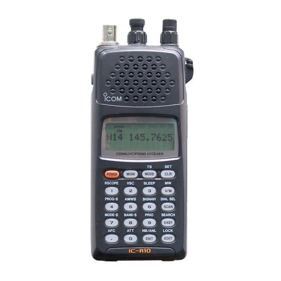
TABLE OF CONTENTS IMPORTANT ... i EXPLICIT DEFINITIONS ... i CAUTIONS ... i UNPACKING ... ii TABLE OF CONTENTS ... iii OPERATING THEORY ... iv OPERATING NOTES ... iv 1 PANEL DESCRIPTION ... 1 – 6 I Front and side panels ... 1 I Top panel ... -
Page 5: Table Of Contents
Electromagnetic radiation which has frequencies of 20,000 Hz (20 kHz*) and above is called radio frequency (RF) energy because it is useful in radio transmissions. The IC-R10 re- ceives RF energy from 0.5 MHz to 1300 MHz* and converts it into audio frequency (AF) energy which in turn actuates a loudspeaker to create sound waves. -
Page 6: Panel Description
PANEL DESCRIPTION I Front and side panels FUNCTION SWITCH (pgs. 5, 6) While pushing [FUNC], the sec- ondary functions of switches and controls can be accessed. FUNCTION DISPLAY (p. 3) Indicates the operating condition. KEYPAD (pgs. 5, 6) Numeral and other function keys for tuning and activating func- tions. -
Page 7: I Top Panel
I Top panel ANTENNA CONNECTOR (p. 9) Connects the supplied flexible antenna. Be careful when con- necting an external antenna (See Operating Notes, p. iv). VOLUME CONTROL [VOL] (p. 10) Adjusts the audio output level. SQUELCH CONTROL [SQL] (p. 11) ➥Varies the squelch threshold point for audio mute. -
Page 8: I Function Display
PANEL DESCRIPTION I Function display MEMO EASY AT T... - Page 9 q SLEEP TIMER INDICATOR Appears while the sleep timer is activated (p. 66). w FUNCTION INDICATOR Appears while the function ([FUNC]) switch is pushed. e MEMORY MODE INDICATOR Appears while in memory mode (p. 23). r VFO MODE INDICATOR Appears while in VFO mode (p. 11). t RECEIVE MODE INDICATOR Indicates the selected receive mode (p.
-
Page 10: I Keypad
PANEL DESCRIPTION I Keypad Push for 1 sec. to toggle power ON and OFF. Opening mes- POWER sage appears for 1 sec. after power ON Push and hold this switch to force the squelch open MONI Selects a receive mode: FM, AM, USB, LSB, CW or WFM MODE (p. -
Page 11: Panel Description ......................................................... 1
PRIMARY FUNCTION BSCOPE When FM receive mode is selected in VFO mode: toggles the band scope function Toggles the VSC function ON and OFF SLEEP Selects the sleep timer conditions PROG-S BSCOPE SLEEP In VFO mode: sets program scan edge frequencies for programmed scan AMWS PROG-S AMWS... -
Page 12: Ni-Cd Batteries And Accessories
Ni-Cd BATTERIES AND ACCESSORIES I Charging Ni-Cd batteries The supplied Ni-Cd batteries are rechargeable and can be charged approx. 300 times. Charge the batteries before first operating the receiver or when the batteries become ex- hausted. If you want to be able to charge the batteries more than 300 times, the following points should be observed: 1. -
Page 13: I Battery Installation
I Battery installation Install 4 AA (R6) size batteries as illustrated below. Remove the cover from the receiver. Install 4 AA (R6) size dry cell, alkaline or the supplied Ni-Cd batteries into the receiver. CAUTION: Make sure the polarity of the batteries is cor- rect before installing. -
Page 14: Ni-Cd Batteries And Accessories ............................ 7
Ni-Cd BATTERIES AND ACCESSORIES I Accessory attachment Antenna Insert the supplied antenna into the antenna connector and rotate the an- tenna as shown in the diagram below. Keep the jack cover attached when jacks are not in use to avoid bad contacts. -
Page 15: Basic Operation
I General Operating the IC-R10 is easy. However, in order to get the most out of its oper- ating potential, please go through the following procedures, step-by-step. Then, try the examples contained at the end of this chapter. What is VFO? - Page 16 BASIC OPERATION 3. Adjust the squelch Rotate [SQL] maximum counter- clockwise, then rotate it clockwise until audio is just muted when receiv- ing no signal for FM, WFM or AM mode. (see right page) What is squelch? A squelch circuit allows you to mute undesired noise while receiving no signal and emit audio while receiving signals.
-
Page 17: I Selecting A Receive Mode
Each mode has its own physical properties that de- termine to some degree its uses. The IC-R10 receives the 6 most common modes: AM, FM, WFM, USB, LSB and CW. When you want to tune a station, you MUST set the receive mode first. The table below shows common uses for each mode. -
Page 18: I Selecting A Tuning Step
BASIC OPERATION I Selecting a tuning step What are tuning steps? Tuning steps are the frequency change increments when you rotate the tuning control or operate a scan. The following steps are available: 0.1, 0.5, 1, 5, 6.25, 8, 9, 10, 12.5, 15, 20, 25, 30, 50, 100 kHz and user programmable tuning steps (p. -
Page 19: I Tuning A Frequency (Via The Keypad)
I Tuning a frequency (via the keypad) When you know the exact frequency you want to listen to, the quickest way to tune it is by direct keypad entry. Remember that the frequency must be between 0.5 MHz and 1300 MHz. The diagram below shows the correla- tion between the function display fre- quency digits and the frequency. -
Page 20: I Tuning A Frequency (Via The Dial)
BASIC OPERATION I Tuning a frequency (via the dial) When you want to listen to frequencies near the displayed frequency, the easi- est way to tune them is with the tuning dial. All signals have what is called an “oc- cupied bandwidth.”... -
Page 21: I Dial Select Steps
I Dial select steps What are dial select steps? When tuning with the dial, if you want to change the fre- quency faster than the selected tuning step can, use the dial select function. A dial select step is an increment of frequency change much like a tuning step is. -
Page 22: I Band Scope Function
BASIC OPERATION I Band scope function What is the band scope function? The band scope detects signal availability in the range of ±5 channels (up to ±100 kHz) from the displayed frequency, and displays the result on the multi function dot-matrix display. This gives you a visual reference of current band conditions. - Page 23 Set band scope function q While pushing [FUNC], push [ BSCOPE]. higher freq. lower freq. displayed freq. Repeat the above step or push [CLR] to turn OFF the band scope function. signal strength BASIC OPERATION...
-
Page 24: I Listening Example 1
BASIC OPERATION I Listening example 1 — television broadcast in WFM mode 1. Turn power ON Push [POWER] for 1 sec. to turn power ON. 2. Select VFO Push [CLR] or [V/M] to select VFO mode. 3. Adjust volume Rotate [VOL] to obtain the desired level of audio output. - Page 25 (Example 59.75 MHz) 7. Tune the station Use the keypad to enter the fre- quency — (example 59.75 MHz). [Example] (Example 59.25 MHz) 7-1. Tune the station Enter the frequency from the 100 kHz digit when you want to change below the 1 MHz digit only —...
-
Page 26: I Listening Example 2
BASIC OPERATION I Listening example 2 — airband broadcast in AM mode 1. Turn power ON Push [POWER] for 1 sec. to turn power ON. 2. Select VFO Push [CLR] or [V/M] to select VFO mode. 3. Adjust volume Rotate [VOL] to obtain the desired level of audio output. - Page 27 (Example 118.00 MHz) 7. Tune the station Enter a frequency of 118.0000 MHz* using the keypad (p. 14). *Check listings for your area. (Example 118.925 MHz) 7-1. Tune the station Enter the frequency from the 100 kHz digit when you want to change below the 1 MHz digit only —...
-
Page 28: Memory Mode
MEMORY mode. The IC-R10 has 1000 memory channels for your conve- nience. They are divided into 18 banks: BANKS A to P con- tain 50 channels each for normal usage, while BANKS Q and R contain 100 channels each for auto-memory write scan (p. -
Page 29: I Setting A Bank And Memory Channel
I Selecting a BANK and memory channel Selecting a BANK channel When your desired memory channel is not stored or you do not want to store a frequency in the displayed BANK, you must change the BANK number. While pushing [FUNC], rotate [DIAL]. Selecting a memory channel—1 If you want to recall a memory chan-... -
Page 30: I Programming A Memory Channel-1
MEMORY MODE I Programming a memory channel — 1 This is the quickest way to memorize a received frequency, along with its re- ceive mode and other information. When you memorize the frequency in this way, the previously memorized data is replaced with the new data. -
Page 31: I Programming A Memory Channel-2
I Programming a memory channel — 2 This is the simplest method to memo- rize the received frequency along with its receive mode and other information. 1. Setting receive conditions q Select VFO mode (p. 11). w Set the frequency and receive mode (p. -
Page 32: I Programming A Memory Channel-3
MEMORY MODE I Programming a memory channel — 3 This is the easiest way to memorize the received frequency, mode and other information along with memory, BANK names, scanning condition, etc. in one operation. 1. Set up q Set the frequency you want to program in VFO mode. w While pushing [FUNC], push [ ory write mode. - Page 33 3. Programming details — cont. 3 Push [EDIT], then rotate [DIAL] to select receive mode. 4 Push [EDIT], then rotate [DIAL] to select the skip scan condition. t Push [EDIT], then rotate [DIAL] to select the attenuator condition. y Push [EDIT], then rotate [DIAL] or enter alphanumeric charac- ters to program a BANK name.
-
Page 34: I Programming Example 1
MEMORY MODE I Programming example 1 — 1. BANK and memory channel setting q Push [V/M] to select MEMORY mode. w While pushing [FUNC], rotate [DIAL] to select BANK “B”. MEMO FUNC [DIAL] e Push [0] and [7] to enter the mem- ory channel number. -
Page 35: I Programming Example 2
I Programming example 2 — 1. Setting the frequency q Push [V/M] to select VFO mode. w Push [MODE] one or more times to select WFM mode. MODE e Push numeral keys or rotate [DIAL] to set the frequency to 59.75 MHz. -
Page 36: I Programming Example 3
MEMORY MODE I Programming example 3 — 1. Setting the frequency q Push [V/M] to select VFO mode. w Rotate [DIAL] or push numeral keys to enter 121.5 MHz. (121.5 MHz, EMER.,AM, SKIP: OFF, ATT: OFF, Aviation to channel F01) 2. - Page 37 3. Programming details — cont. t Push [EDIT] to change the re- ceive mode item. y Rotate [DIAL] to select AM mode, then push [EDIT] to change the item. [DIAL] u Rotate [DIAL] to select the OFF position for SKIP setting, then push [EDIT].
-
Page 38: I Memory Copy
MEMORY MODE I Memory copy What is the memory copy function? The memory copy function copies the contents (minus BANK names) of the selected memory channel to VFO or to another memory channel. This is quite useful when you want to search for signals around the displayed frequency or when you want to edit memory channels. -
Page 39: I Copying Example 1
I Copying example 1 (59.7500 MHz, WFM, A45 to VFO) 1 Push [V/M] to select memory mode (p. 23). 2 Select the memory channel A45 (p. 24). 3 While pushing [FUNC], push [ MW] for 2 sec. to copy (V/M) the contents of memory A45 to VFO. -
Page 40: Scanning Operation
SCANNING OPERATION I General Scan types The IC-R10 has 2 major scan types: PROGRAMMED SCAN and MEMORY SCAN. These, in turn, can be subdivided into 3 variations of each, making a total of 6 scan operations. Additional scanning functions are available to “fine tune”... - Page 41 PROGRAM SCAN Programmed edges Repeatedly scans between two user-programmed fre- quencies (scan edges). BANK SCAN Blank Repeatedly scans all memory channels in the selected BANK except blank channels. AUTO-MEMORY WRITE SCAN Programmed scan edges Same as PROGRAMMED SCAN except that paused fre- quencies are automatically stored in memory channels Q00–Q99.
-
Page 42: I Before Scanning
SCANNING OPERATION I Before scanning Set the following conditions before scanning. INFORMATION What happens when you rotate the tun- ing dial during scanning? While scanning— Scanning direction is changed. Example: If you rotate [DIAL] counterclockwise while scanning up (frequency/memory channel number increase), changes to down scanning (fre-... - Page 43 Set the VSC Set the VSC ON if necessary. While pushing [FUNC], push [ VSC] (VSC indicator ap- pears). FUNC SIGNAVI While pushing [FUNC], push [(2)VSC) to turn OFF the VSC (VSC indicator disappears). What is VSC? The VSC (Voice Scanning Control) pauses a scan only when modulated signals are received.
-
Page 44: I Full Scan
SCANNING OPERATION I Full scan This is the simplest scanning operation, searching the full fre- quency range (0.5–1300 MHz) in the selected receive mode and tuning step. Start and stop the scan 1 Push [V/M] to select VFO mode. (p. 11) 2 Push [SCAN] to start SCAN scanning. -
Page 45: I Program Scan
I Program scan This is the most useful basic scan for searching over a spec- ified frequency range. 1. Select program scan channel q Push [V/M] to select VFO mode (p. 11). w While pushing FUNC [FUNC], push PROG-S]. PROG-S Rotate [DIAL] to se- lect the program scan [DIAL]... -
Page 46: I Auto Memory Write Scan
SCANNING OPERATION I Auto memory write scan This scan is useful for searching a specified frequency range and automatically storing busy frequencies into memory channels. The same frequency ranges used for program scan are used for auto memory write scan. 1. - Page 47 During auto-memory write scanning: 1 Busy (paused) frequencies are automatically stored into BANK Q memory channels. 2 The scan is automatically cancelled when BANK Q becomes full. 3 Unmodulated or beat signals may not be stored into mem- ory channels when the VSC function is turned ON. 4 While pushing [FUNC], push [ MW] when unwanted sig- (V/M)
-
Page 48: I Bank Scan
SCANNING OPERATION I BANK scan Scans all stored frequencies into a specified BANK, except for SKIP channels. 1. Select BANK scan and BANK number q Push [V/M] to select MEMORY mode (p. 23). w While pushing FUNC [FUNC], push BANK-S [(8)BANK-S]. -
Page 49: I Mode Select Scan
I Mode select scan Scans all stored frequencies that have the specified receive mode, except SKIP channels. 1. Select mode select scan and mode q Push [V/M] to select MEMORY mode (p. 23). w While pushing MEMO FUNC [FUNC], push MODE-S MODE-S]. -
Page 50: I Skip Function
SCANNING OPERATION I Skip function Two skip functions are available as fol- lows: 1. Program skip function Used with full, program and auto-mem- ory write scans, this function allows you to skip specified frequencies stored in BANK R (skip function must be ON for these channels). -
Page 51: I Signavi Function
I SIGNAVI function The SIGNAVI function activates while paused during full, program or auto- memory write scans in FM mode. It searches for busy frequencies up to 100 kHz* (+100 kHz when scanning up, –100 kHz when scanning down) from the paused frequency (f ), then jumps to the next busy frequency (f... -
Page 52: Priority Watch
PRIORITY WATCH I General What is priority watch? Priority watch checks for signals on a priority frequency while listening to another frequency or, while searching one or more frequencies or memory channels. When receiving a signal on the priority channel, priority watch pauses for 5 sec. - Page 53 FULL SCAN WATCH/PROGRAM SCAN/AUTO-MEMORY WRITE SCAN WATCH MEMORY SCAN/BANK SCAN/MODE SELECT SCAN WATCH While scanning the full frequency range or a programmed fre- quency range, priority watch checks for signals on the priority fre- quency every 5 sec. • When the skip function is ON, skips specified frequencies. •...
- Page 54 PRIORITY WATCH 1. Program a priority channel 144.0000 MHz is initially programmed by default. q Select the frequency (ex.) you want to program into priority channel mode (p. 11) or MEMORY mode (p. 23). w While pushing FUNC [FUNC], push PRIO PRIO] for 2 sec.
-
Page 55: Easy Mode
I General The IC-R10 has an EASY mode which provides simple operation by only scan- ning programmed frequency ranges. When you select EASY mode, 1 of 10 pre-programmed frequency ranges can be selected. 10 different frequency ranges are pro- grammed for EASY mode operation in some transceiver versions;... -
Page 56: Edit Function
EDIT FUNCTION I General The edit function is used for arranging memorized contents into the following channels: Memory channels Program/auto-memory write scan channels EASY mode channels I Memory channel edit You can store the following items into a memory channel: 1. - Page 57 Memory channel edit flow chart MEMO EDIT EDIT Push for 2 sec. Fixed contents will be cleared. MEMO MEMO EDIT EDIT MEMO MEMO EDIT MEMO MEMO EDIT EDIT FUNCTION EDIT EDIT...
-
Page 58: Set Frequency
EDIT FUNCTION I Memory channel edit 1. Enter memory edit mode q Push [V/M] to select MEMORY mode, then select the memory channel (pgs. 23, 24). w Push [EDIT] to enter memory edit mode. 2. Set frequency q Enter the frequency via the key- pad or by rotating [DIAL]. -
Page 59: Set Attenuator
4. Set receive mode and skip condition q Rotate [DIAL] to select receive mode. MEMO [DIAL] w Push [EDIT] to change the item. e Rotate [DIAL] to select skip condi- tion. MEMO [DIAL] r Push [EDIT] to change the item. 5. -
Page 60: I Program Scan Channel Edit
EDIT FUNCTION I Program scan channel edit Arrange memorized contents into program scan channels 00 to 19. You can edit the following items: 1. Channel names: ( Set channel names for programmed frequency range; up to 8 characters per name. 2. - Page 61 Program/auto-memory write scan and EASY mode channel edit flow chart EDIT EASY EDIT Push for 2 sec. Fixed contents will be cleared. EASY EDIT EDIT EASY EDIT EASY EDIT EDIT FUNCTION EASY EDIT EASY EDIT EASY...
-
Page 62: I Program Scan Or Easy Mode Channel Edit
EDIT FUNCTION I Program scan or EASY mode channel edit 1. Enter edit mode q Push [V/M] or [EDIT] to select VFO or EASY mode (p. 11 or 50). w While pushing [FUNC], push PROG-S] or [ AMWS] to se- lect program or auto-memory write scan mode;... - Page 63 4. Set end frequency q Enter the start frequency via the keypad or [DIAL]. w Push [EDIT] to change the item. either EASY [DIAL] digit 5. Set receive mode and tuning step q Rotate [DIAL] to select receive mode. either EASY [DIAL] w Push [EDIT] to change the item.
-
Page 64: Set Mode
SET MODE I General Set mode flow chart What is SET mode? SET mode is accessed from VFO, FUNC MEMORY or EASY mode and allows MEMO you to modify certain receiver condi- tions to suit your operating require- ments. EASY Adjusting these settings to your own in- dividual preferences allows you to “cus- tomize”... - Page 65 Entering SET Opening message mode While pushing [FUNC], Rotate [DIAL] to toggle push [ SET] to enter opening message ON or (CLR) SET mode. OFF. Push [EDIT] to select next item. Beep audio Display contrast Rotate [DIAL] to set beep Rotate [DIAL] to adjust the audio ON or OFF.
- Page 66 SET MODE Backlight condition Rotate [DIAL] to set LCD and key backlight condi- tions. Program skip Memory skip condition condition Rotate [DIAL] to toggle the Rotate [DIAL] to toggle the program skip scan condi- memory skip scan condi- tion ON or OFF. tion ON or OFF.
- Page 67 Scan delay CI-V address condition Rotate [DIAL] to set the Rotate [DIAL] to select the scan pausing time. CI-V address from 01 to CI-V baud CI-V transceive Rotate [DIAL] to select CI- Rotate [DIAL] to toggle CI- V baud from 300, 1200, V transceive function ON 4800, 9600 and 19200 bps.
-
Page 68: Other Functions
OTHER FUNCTIONS I Low battery indicator The low battery indicator activates when the installed batter- ies fall to a specified voltage level. The receiver emits beeps and displays “ pacity is low. Beeps sound once every 10 sec. and are syn- chronized with the beep setting in SET mode (p. -
Page 69: I Monitor Function
I Monitor function The monitor function releases the squelch or VSC mute mo- mentarily when very weak signals are received without having to re-adjust the squelch manually. Set monitor While pushing [MONI], squelch mute is released; when the VSC function is ON, both squelch and VSC mute are re- leased. -
Page 70: I Att Function
OTHER FUNCTIONS I ATT function The ATT (attenuator) function protects desired signals from distorting when excessively strong signals, such as broad- cast, pager signals, etc. are nearby. This setting can be mem- orized into memory channels. Set ATT While pushing [FUNC], push [ function ON and OFF. -
Page 71: I Sleep Timer
I Sleep timer function* The sleep timer activates after a specified time elapses, automatically turning the re- ceiver power OFF. Set sleep timer q While pushing [FUNC], push [ SLEEP] one or more times to set the sleep timer condition. w Release [FUNC] to set the selected condition. -
Page 72: I Memory Search Function
OTHER FUNCTIONS I Memory search function The memory search function searches memory channels using channel names. This is useful for recalling memory channels when you forget their channel number. Enter memory search mode q Push [V/M] to select MEMORY mode (p. 23). w While pushing [FUNC], push [ FUNC SEARCH... -
Page 73: Selecting A Memory Channel
Searching Push [SCAN] to start memory channel search. • Only the first one or two characters are needed to start a search. Smaller channel numbers are displayed first in cases where two or more channels start with the same characters. •... -
Page 74: I Auto Mode And Ts Function
OTHER FUNCTIONS I Auto mode and TS function The auto receive mode select and auto tuning step select functions are optionally available. This function can be set up and modified by programming from a computer using the optional CS-R10 CLONING SOFTWARE pre-programmed. -
Page 75: I Resetting The Cpu
I Resetting the CPU There are 2 ways to reset the CPU as follows: PARTIAL RESET: When you want to initialize the operat- ing conditions (VFO frequency, VFO settings, SET mode contents) without clearing the memory, program scan, EASY mode and auto TS/mode set- tings, a partial reset function is available for the receiver. -
Page 76: I Data Cloning
OTHER FUNCTIONS I Data cloning The IC-R10 has receiver-to-receiver data cloning capability. This function is useful when you want to copy all of the programmed contents from IC-R10 to another. An optional OPC-474 CLONING CABLE is required. In addition, the optional CS-R10... -
Page 77: Alphanumeric Key Assignment
ALPHANUMERIC KEY ASSIGNMENT Corresponding Alphanumeric Character Keypad Input No modifier key While pushing [FUNC] (Q), (Z), (q), (A), (B), (C), (a), (D), (E), (F), (d), (G), (H), (I), (g), (J), (K), (L), (j), (M), (N), (O), (m), (P), (R), (S), (p), (T), (U),... -
Page 78: Control Commands
CONTROL COMMANDS I General The IC-R10 can be connected to a PC via the PC’s RS-232C port using an optional CT-17 allows you to control the receiver from the PC and/or transfer data from the receiver to the PC. Control is provided via Icom’s CI-V Communication Interface. - Page 79 CONTROL COMMANDS Computer Power supply Optional 9–15VDC BC-25 RS-232C cable CT-17 to [CI-V] IC-R10 CI-V connection example...
-
Page 80: Troubleshooting
TROUBLESHOOTING If your receiver seems to be malfunctioning, please check the following points before sending it to a service center. PROBLEM POSSIBLE CAUSE No power comes on. • The installed batteries are exhausted. (A slight current flows in the circuits even when the power is OFF.) •... - Page 81 PROBLEM POSSIBLE CAUSE Cannot start scanning. • [SQL] is rotated too far clockwise. • Incorrect receive mode (LSB, USB or CW) is se- lected. • Scan edges are set to the same frequencies. • 2 or more memory channels have not been pro- grammed.
-
Page 82: Specifications
SPECIFICATIONS GENERAL Frequency coverage Tuning steps : 0.1, 0.5, 1, 5, 6.25, 8, 9, 10, 12.5, 15, 20, 25, 30, 50 and 100 kHz or user programmable (0.1–999.99 kHz/0.1 kHz steps) Number of mem. channels : 1000 Receive modes : FM, AM, WFM, USB, LSB, CW : BNC (50 Ω) Antenna connector Power supply requirement... -
Page 83: Options
• CS-R10 + OPC-478 CLONING SOFTWARE Allows you to transfer data from memories, etc., quickly and easily edit and store data via an IBM compatible PC. • LC-140 CARRYING CASE Protects the receiver from everyday wear and tear. • CT-17 V LEVEL CONVERTOR For receiver remote control using an IBM compatible per- sonal computer. - Page 84 A-5410H-1EX-t Printed in Japan 6-9-16 Kamihigashi, Hirano-ku, Osaka 547 Japan Copyright 1996 by Icom Inc.
Need help?
Do you have a question about the IC-R10 and is the answer not in the manual?
Questions and answers