
Summary of Contents for REVELTRONICS UTCOMP-3
- Page 1 UTCOMP-3 & UTCOMP-PRO User & assembly manual. Last update (v3.8.0): 2020-04-17 www.REVELTRONICS.com...
-
Page 2: Table Of Contents
Please read this manual carefully before device using. Contents Technical data and requirements ............- 5 - Assembly manual ................- 11 - 2.1. General remarks .................................... - 11 - 2.2. Pinout......................................- 12 - 2.3. Pinout description ..................................- 13 - 2.4. - Page 3 3.1. Quick start ....................................- 23 - 3.2. First start in the vehicle .................................. - 25 - 3.3. Calibration of speed and fuel consumption ............................- 26 - 3.3.1. Initial calibration ..................................- 26 - 3.3.2. Accurate calibration - achieving accuracy better than 1% ......................- 28 - 3.4.
- Page 4 3.6.5. Alerts ...................................... - 39 - 3.6.6. Trip summary ..................................- 40 - 3.6.7. Units change .................................... - 40 - 3.6.8. Battery voltage (Voltmeter) ............................... - 40 - 3.6.9. User defined screens................................. - 41 - 3.6.10. Adjusting brightness ................................- 42 - 3.6.11.
-
Page 5: Technical Data And Requirements
1. Technical data and requirements Universal Trip Computer (UTCOMP) developed and manufactured by REVELTRONICS is an on-board computer designed for wide range of vehicles. It takes information from main sensors then process data and sends to LCD or OLED screen with user friendly interface. - Page 6 UTCOMP-3 vs. UTCOMP-PRO LCD 122x32pix (2,5") OLED 256x64pix (3,2") Compatible displays: OLED 122x32pix (2,3") (+ HUD mode available) Digital inputs: (e.g. speed signal, fuel consumption, rpm etc.) Digital outputs: (e.g. relay switch control 5V@100mA) Analog sensor inputs 0-5V: (high impedance)
- Page 7 Display dimensions [mm]: LCD 2,5" (left) and OLED 2,3" (right) for UTCOMP-3*: *NOTE: on the bottom side is soldered socket for IDC40 tape. Display dimensions [mm]: OLED 3,2" for UTCOMP-PRO**: Check comparison video on youtube: https://www.youtube.com/watch?v=dOOXRnN7p0c **NOTE: on the bottom side is soldered socket for IDC16 tape.
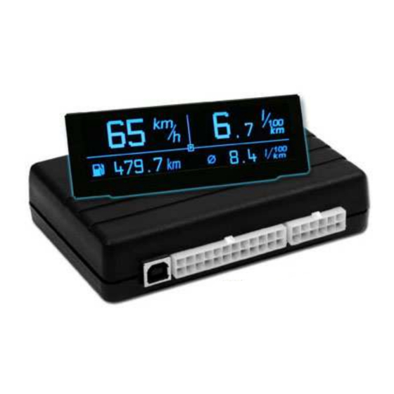
- Page 8 Module dimensions: UTCOMP-3: 90 mm Width: 65 mm Depth: 20 mm Height: Module dimensions: UTCOMP-PRO: 120 mm Width: 83 mm Depth: 29 mm Height: - 8 -...
- Page 9 Features & Requirements: To activate following features of the UTCOMP some signals have to be connected. What kind of signal for each function is required shows the table below. You should connect only what are you interested with. You do not have to connect all signals. Group Example features Requirements...
- Page 10 • independent measurements of distance & fuel consumption for PB (ref. to section 2.4.9) and LPG (with auto-recognition of current fuel supply) + req. of groups III & IV • fuel level in fuel tank(s) req. of groups III, IV, (V) (differential •...
-
Page 11: Assembly Manual
2.1. General remarks UTCOMP-3 has a 24-pin MOLEX connector. UTCOMP-PRO has a 24-pin and 12-pin MOLEX connectors. The kit comes with a plug with cables to solder. Pay special attention to the numbered pins. All cables used to be install must be the dedicated automotive (FLRY), recommended 0.35 – 0.5 mm cross-section with insulation resistant to mechanical damage (abrasions, cracks etc.). -
Page 12: Pinout
2.2. Pinout Connectors pinout (module side): Plugs pinout (wire side): Connector "A" (UTCOMP and UTCOMP-PRO) Connector "B" (UTCOMP-PRO) LABEL LABEL LABEL LABEL SW_GND DigInUser (RPM) DigOutUser (5V max 100mA) SW_3 Adc3 (0-5V) AdcVcc2 (0-5V, +5V PULL-UP) SW_2 SW_1 Adc4 (0-5V) Adc5 (0-30V) DS18B20-A_GND DS18B20-B_GND... -
Page 13: Pinout Description
2.3. Pinout description GROUP DESCRIPTION Battery A12 (-), A24 (+) power supply for the device, safe range is +8V...+32V DC (0,6A fuse is built-in in UTCOMP module) Ignition (A23) positive voltage from ignition switch (0V - low state, 5V and more - high state) - wake up UTCOMP from sleep mode output for the three-button keypad (monostable switches, powered +5V from UTCOMP, press button shorts to GND) SW... -
Page 14: Wiring Diagram
2.4. Wiring diagram - 14 -... -
Page 15: Power Supply
2.4.1. POWER SUPPLY Pin A24 connect to +12V/+24V (BAT), and pin A23 to +12V/+24V ignition switch (voltage occurs when the ignition key is turned on). Pin A12 connect to the vehicle ground (GND). The power line is already protected with 0,63A fuse built-in UTCOMP, so additional fuse is not necessary. 2.4.2. -
Page 16: Buzzer
Isolation wire leads are recommended using hotair shrink insulation . In UTCOMP-3 application you can associate sensors with temperatures, so connection order does not matter. For inside temperature sensor we recommend to place it in the place of free heating air, sun rays please take a look at short video tutorial: https://www.youtube.com/watch?v=R8Z66qtYowA... -
Page 17: Fuel Consumption Signal
Additional tutorial is available on forum: http://www.reveltronics.com/forum/viewtopic.php?f=28&t=120 2.4.5. FUEL CONSUMPTION SIGNAL Injector control signal (PWM) or dedicated fuel consumption signal (PWM/FREQ) connect to pin A10. There are few places when you should looking... - Page 18 Petrol engines with LPG: • option 1: to the appropriate pin in the ECU connector (petrol injector control) - pinout for ecu connector can be found in electrical documentation (wiring diagrams) of the vehicle. You should not connect directly to injector connector because there is no signal when engine is running on lpg. Diesel engines: In diesel engines you should looking for dedicated fuel consumption signal (PWM or FREQ).
-
Page 19: Vss - Vehicle Speed Signal
• possibility to measure fuel injection timing (from injector ) – max 150V amplitude, • possibility to measure fuel pressure: signal from fuel pressure sensor (it's located on common-rail tube) connect to Adc1 or Adc2 inputs and set input configuration as "fuel pressure sensor (diesel common-rail)" 2.4.6. -
Page 20: Headlights Or Fan Cooler
2.4.8. ANALOG SENSORS - Adc and AdcVcc inputs UTCOMP-3 supports 3 analog inputs (Adc1, Adc2, AdcVcc1), UTCOMP-PRO supports 7 analog inputs (Adc1, Adc2, Adc3, Adc4, Adc5, AdcVcc1, AdcVcc2). Example of use: analog temperature sensors (NTC), boost pressure from MAP/MAF, oil pressure sensor, lambda o2 sensor, AFR readings from wideband o2 controller, exhaust temperature from EGT controller, fuel level, gear indicator etc. -
Page 21: Lpg System
UTCOMP using a dedicated ribbon tape. The tape has a special key so that it cannot be wrong side connected. Standard tape length is 60cm for UTCOMP-3 and 100cm for UTCOMP-PRO. To properly run, the display should be connected before power is connected to the device. -
Page 22: Additional Instructions For Assembly
panel. Display should be assembled in a visible place, as close as possible driver's eye level. Avoid selection of direct sun and very warm places. LCD contrast and refresh rate is optimized for 10-40C temperature range. OLED is characterized with about 180deg. view, high contrast and refresh rate in wide range of temperatures (-40C...+85C). -
Page 23: User Manual
• update: for devices with previous version of firmware. UTCOMP software can be downloaded from manufacturer page (technical support tab) - the same application is for UTCOMP-3 and UTCOMP-PRO - 23 -... - Page 24 Click "Settings" button. Appropriate dialog should popup (similar to that shown in the screenshot below). The program should read the settings from the device. Some options are dedicated only for UTCOMP-PRO so in UTCOMP-3 may be inactive. You can save settings to the device by clicking "Settings ->...
-
Page 25: First Start In The Vehicle
3.2. First start in the vehicle If the installation was performed correctly it you can connect main 24-pin connector to the device. Previously, connect the LCD/OLED connector. When you turn the ignition key, the display should illuminate and show the splash screen. The welcome screen is displayed for 2 seconds, then displays the default user screen (varies depending on the preferences selected in the settings). -
Page 26: Calibration Of Speed And Fuel Consumption
3.3. Calibration of speed and fuel consumption In order to calibrate speed and fuel consumption readings, two constants have to be set: • VSS constant, expressed in meters per pulse [m/imp], • injection constant, expressed in liters per second [l/s]. Calibration assistant built-in UTCOMP application will help you calculate these constants. - Page 27 You can end calibration process at any time. Run UTCOMP application, click "Help" button and go to "Calibration Assistant" tab. You can import collected data from UTCOMP or rewrite it manually (they are displayed in DIAGNOSTICS screen). First step is to calculate VSS constant which is responsible for speed and distance readings.
-
Page 28: Accurate Calibration - Achieving Accuracy Better Than 1
3.3.2. Accurate calibration - achieving accuracy better than 1% Accurate calibration is based on comparing real distance and fuel consumption values with values displayed on UTCOMP. You will calculate percentage difference and make correction of constants. Start UTCOMP application, click "Help" and "Measurement Correction" tab. In order to calibrate speed and distance readings, you need to enter distance counted by UTCOMP and real distance traveled by the... - Page 29 TIPS for calibration: • for accurate calibration it's recommended to make longer distance: tank to full (remember to set proper tank capacity before) reset statistics in tacho screen (distance and average fuel consumption) by long pressing SW3 and follow display instructions, travel long distance (at least 100 km or miles - you don't have to do it single trip), refuel to full and calculate real average fuel consumption from distributor data, make correction using Measurement Correction function in UTCOMP application.
-
Page 30: Menu Navigation
3.4. Menu navigation The device can be controlled using 3-buttons keypad. Depending on the currently selected screen, functions of the buttons may vary: short press - go to the next screen Button 1 (SW1) long press (1s) - change display modes screens (reading screens / user settings mode) short press - action depends on the currently displayed screen Button 2 (SW2) long press (1s) –... -
Page 31: Screen 1 - Temperatures
For vehicles with LPG there is also additional icon on the center of the screen indicating current fuel type (p - petrol, g - lpg). Press SW2 to switch between options displayed in bottom-left corner. Long press SW3 will jump to menu for statistics reset. OLED 2,3" (UTCOMP-3) on the left, OLED 3,2" (UTCOMP-PRO) on the right Following diagram on the next page shows resetting sequence. - Page 32 Notes for the diagram: • you can jump to reset menu from screens: tacho, fuel tanks and user screens, • if you connect fuel level signal than you do not need to enter fuel quantity, • if you do not enter fuel quantity and do not connect fuel level signal than two functions will not work properly: estimated distance to refuel and fuel level in fuel tank (average fuel consumption will still work),...
-
Page 33: Screen 3 - Trip (Daily Counter)
Hold SW3 to reset TRIP statistics or to change fuel cost. LCD 2,5" (UTCOMP-3) on the left, OLED 3,2" (UTCOMP-PRO) on the right Tip: for vehicles with LPG trip measured fuel consumption is averaged from petrol fuel consumption and lpg fuel consumption. -
Page 34: Screen 4 - Trip-Meter For Off-Road
3.5.4. Screen 4 – Trip-meter for off-road Trip-meter for off-road measure accurate distance (in meters) with fast and easy way to reset readings (short SW3 reset DIST, long SW3 reset TOTAL). Button SW2 switch modes: normal / reverse / freeze. LCD 2,5" (UTCOMP-3) - 34 -... -
Page 35: Screen 5 - Fuel Tanks
The fuel level in tanks is visualized on the screen. If the car does not have LPG than only one tank is shown. LCD 2,5" (UTCOMP-3) on the left, OLED 3,2" (UTCOMP-PRO) on the right 3.5.6. Screen 6 – Measurement of acceleration/deceleration Acceleration measurements are made automatically. -
Page 36: Screen 7 - Oscilloscope
(Settings -> Advanced -> Oscilloscope). You can set label and voltage range for each channel. Press SW2 to switch between inputs. Oscilloscope on OLED 2,3" (UTCOMP-3) - on the left, and OLED 3,2" (UTCOMP-PRO) - on the right Typical applications are: signal from lambda o2 sensor (oscillations between lean and reach mixture), boost pressure chart, threshold position sensor or any other voltage signal changing in time. -
Page 37: Screen 8 - Clock
3.5.8. Screen 8 – Clock Dedicated screen with clock will be useful if you assembled display in place of factory watch. On the bottom are displayed also two temperatures: outside and inside the vehicle. Press SW3 to change current font. 3.5.9. -
Page 38: Review Of Other Functions
3.6. Review of other functions 3.6.1. Headlights reminder At the stage of assembly, decide what signal would you like to connect at pin A21 – a signal from headlights or fan cooler. If you choose headlight reminder function, you should connect appropriate signal from headlights relay (+12V headlights on, 0V headlights off). If vehicle speed is greater than 10 [km/h or mph] and headlights will not be turned on, the screen will show a message “Turn headlights on”... -
Page 39: Travel Costs
3.6.3. Travel costs It is possible to calculate travel costs in TRIP screen. For calculation are used: average fuel consumption in trip screen, distance and fuel price (per liter or per gallon). 3.6.4. Black ice alert You should have outside temperature sensor connected. In the case of temperature below two degrees, the outside temperature icon will change (snow instead of clouds). -
Page 40: Trip Summary
3.6.6. Trip summary After each trip summary screen will be displayed (with traveled distance, trip time, fuel consumption and cost). You can change time for how long screen will appear (0-180s). For vehicles with LPG, summary calculations include both fuel types. In TRIP screen there is possibility to switch to current summary screen (SW3) or restore last displayed summary (SW3 once again). -
Page 41: User Defined Screens
3.6.9. User defined screens In UTCOMP application, you can define your own screen. You can decide what to display in each place. In UTCOMP-3 there is available single user screen. In UTCOMP-PRO there are four user screens (different templates). Here is an example of configuration user screen for UTCOMP-3 and UTCOMP-PRO (user-1 has template from tacho screen): Top regions (UL and UR) are single choose. -
Page 42: Adjusting Brightness
3.6.10. Adjusting brightness You can change the brightness of LCD/OLED display. To do this, go to user preferences settings (long press SW1) and then to adjust brightness screen (short press SW1). Adjusting the backlight intensity can be done with a threshold at about 1-2%. By default, the display brightness is set at 80%. - Page 43 Since version v3.7 there is also possibility to download data logs (and draw charts) using Android device and UTCOMP Android application. Please check forum for more information: https://forum.reveltronics.com/viewtopic.php?f=28&t=408 - 43 -...
-
Page 44: Digital Output Control (Digoutuser)
100mA), so in most cases it will be used to control monostable relay switch with 5V coil. Tutorial is available on forum: http://www.reveltronics.com/forum/viewtopic.php?f=28&t=172 3.6.14. Support for additional sensors: pressure, temperature, AFR, EGT etc. There is possibility to connect additional sensors, such as: •... -
Page 45: Settings Device Parameters
3.7. Settings device parameters Important device parameters can be entered from the screens. To change all parameters of the device in a convenient way connect the USB cable to the device (you can left usb cable led out in car in an accessible place) and run the UTCOMP application on your PC. How to run and manage the program is explained in Section 3.1. -
Page 46: User Preferences
• I/O configuration (settings of additional signals and sensors connected to UTCOMP) 3.7.2. User preferences In this group you will find settings associated with the user preferences, such as: language, key press sound, current fuel consumption average time, sleep mode configuration, units change, welcome screen (text or bitmap), acceleration/deceleration thresholds. 3.7.3. -
Page 47: Utcomp Android
4. UTCOMP Android Android application is additional layer for user interface for UTCOMP-3 and UTCOMP-PRO modules (v3.6+). UTCOMP module is responsible for reading and processing data, while Android App is working as additional user interface (displaying additional gauges). There is also possibility to visualize data logs from UTCOMP-PRO data logger –... -
Page 48: Attachments
Using application calculator you can expect about 1-3C accuracy in provided temperature range (and unknown accuracy outside the range) . If you have more data points (sensors characteristics) than you can use our Excel calculator which is more accurate (and you will see calibration errors): http://www.reveltronics.com/forum/viewtopic.php?f=28&t=58 - 48 -... -
Page 49: Appendix B - Troubleshooting
5.2. APPENDIX B - Troubleshooting Each unit is tested by the manufacturer. The following table lists examples of issues and possible solutions: problem possible solution • After mounting No power supply, • connecting UTCOMP in the No power at ignition, •... - Page 50 • UTCOMP does not count No fuel consumption signal at input or wrong settings (type of fuel consumption signal: PWM/FREQ , the time of injection. plus/gnd controlled) Please check the connection (if signal appears at the input of UTCOMP) and check fuel consumption type configuration.
- Page 51 • During acceleration Reverse type of fuel consumption signal fuel consumption If in UTCOMP application, type of fuel consumption signal has been set to "controlled by GND" then select decreasing instead controlled by +"). increasing • Wrong type of fuel consumption signal (PWM/FREQ) In most cases PWM signal should be choosen.
-
Page 52: Appendix C - Frequently Asked Questions (Faq)
Q: Can I use my own display, e.g. a different color or size? A: UTCOMP-3 is compatible with all graphic displays with a resolution 122x32pix based on the controller NJU6450, SED1520 and related. UTCOMP-3 works also with OLED displays with SSD1305 driver. UTCOMP-PRO is compatible with all OLED displays with a resolution 256x64pix and SSD1322 controller. - Page 53 Q: Where to find the signal from the VSS speed sensor? A: If you have an electronically controlled counter (e.g., on "cable") the easiest and fastest way is to check whether such a signal is connected to the radio socket (some radios have the option volume up with increasing speed) – the ISO pin no.1, designated generally as VSS, Vehicle Speed, GALA, GAL, etc.
Need help?
Do you have a question about the UTCOMP-3 and is the answer not in the manual?
Questions and answers