Sign In
Upload
Download
Table of Contents
Contents
Add to my manuals
Delete from my manuals
Share
URL of this page:
HTML Link:
Bookmark this page
Add
Manual will be automatically added to "My Manuals"
Print this page
×
Bookmark added
×
Added to my manuals
Manuals
Brands
M&C Manuals
Laboratory Equipment
SP2000
Instruction manual
M&C SP2000 Instruction Manual
Hide thumbs
Also See for SP2000
:
Instruction manual
(19 pages)
1
2
Table Of Contents
3
4
5
6
7
8
9
10
11
12
13
14
15
16
17
18
19
20
21
22
23
24
25
26
27
28
29
30
31
32
33
34
35
36
37
38
39
40
41
42
43
44
45
46
47
48
49
50
51
52
53
54
55
56
57
58
59
page
of
59
Go
/
59
Contents
Table of Contents
Bookmarks
Table of Contents
Table of Contents
General Information
Declaration of Conformity
Safety Instructions
Warranty
Used Terms and Signal Indications
Introduction
Serial Numbers
Technical Data
Application
Description
Probe Design of the Heated Version
Sample Gas Connection
Figure 1 Design of Basic Version SP2000-H
Temperature Controller
Sample Tube and Prefilter Possibilities
Receipt of Goods and Storage
Preparation for Installation
Mounting
Check of the Filter Element
Figure 2 Mounting Possibilities SP2000
Figure 3 Cross-Sectional Drawing SP2000-H
Mounting of the Screwed Connector at the Sample Outlet
Figure 4 Removing the New Filter Housing Lid
Figure 5 Mounting of Screwed Connector at Sample Outlet
Mounting of Probe with Sample Tube or Prefilter
Figure 6 Mounting of Sample Tube or Prefilter
Mounting of Sample Line
Figure 7 Mounting of Heated Sample Line
Connection of Option Test Gas Feeding or Blow Back Line
Figure 8 Connection Test Gas Feeding or Blow Back Line
Connection Option Pneumatic Drive MS1 or MS3
Electrical Connections
Standard Version with Internal Capillary Tube Thermostat
Version with PT100 or Thermocouple (Option)
Figure 9 Electrical Connection for SP2000-H, SP2300-H and SP2400-H with Thermostat Controller
Figure 10 Electrical Connection of External Temperature Controller E.g. 70304G
Starting
Figure 11 Electrical Connection Electronic Controller 70304G
Gas Sample Probe SP2300-H
Option Calibration Gas Feeding and Blow Back
Option Check Valve /R
Option 3/2 Way Ball Valve /3VA and /3VA320
Figure 12 Calibration Gas Feeding
Option Ball Valve Drives
Option Pneumatic Drive MS1 or MS3 When Using a 2/2-Way Ball Valve /VA
Figure 13 Pneumatic Drive for 2/2-Way Ball Valve
Option Pneumatic Drive MS1 or MS3 When Using a 3/2-Way Ball Valve /3VA
Figure 14 Pneumatic Drive for 3/2-Way Ball Valve
Option Electrical Ball Valve Drive
Option Solenoid Valve Units for Blow Back, Test Gas Feeding and Control of the Pneumatic Drives
Figure 15 Electrical Connection for Electrical Ball Valve Drive
Figure 16 Connections Solenoid Valve Unit 2
Figure 17 Connections Solenoid Valve Unit 3
Option Drive Unit 234B for the Solenoid Valve Units
Figure 18 Wiring Plan of Control Unit 234B
Maintenance
Changing Filter Element and Checking Sealings
Figure 19 Filter Elements and Gaskets
Change of the Optional Prefilter
Change of Heating Cartridge and Thermostat
Figure 20 Position of Thermostat and Heating Cartridge
Figure 21 Position of Fixing Screws of Connection Box, Thermostat Sensor and Heating Cartridge Carrier Plate
Figure 22 Dismounted Electrical Connection Box with Heating Cartridge and Thermostat Sensor
Switching off
Proper Disposal of the Device
Figure 23 Adjustment of the Mechanical Stop at the Thermostat Controller
Spare Part List
Connection and Mounting Data
Appendix
Figure 24 SP2000-H Basic Version
Figure 25 SP2000-H with Options
Sp2300-H
Figure 27 SP2300-H Filter Elements
Figure 28 High Temperature Tube Aluminium Oxide AO
Figure 29 Heated Sample Tubes SP30-H
Figure 30 Test Gas Feeding and Blow Back Possibilities
Figure 31 SP2000-H/3VA/MS-NC-B
Figure 32 SP2000-H/3VA/MS-NC-C
Figure 33 SP2000-H/3VA/MS-NO-B
Figure 34 SP2000-H/3VA/MS-NO-C
Advertisement
Quick Links
Download this manual
®
Gas Sample Probe Series SP
SP2000, SP2000-H, SP2300-H,
SP2400-H
serial number 10283 and higher
Instruction Manual
Version 1.00.03
Table of
Contents
Previous
Page
Next
Page
1
2
3
4
5
Advertisement
Table of Contents
Need help?
Do you have a question about the SP2000 and is the answer not in the manual?
Ask a question
Questions and answers
Related Manuals for M&C SP2000
Measuring Instruments M&C SP Series Instruction Manual
Option/hp25/400 c for operating pressure of 25 bar max. for gas sample probe (19 pages)
Laboratory Equipment M&C SP Series Instruction Manual
(59 pages)
Laboratory Equipment M&C SP Series Instruction Manual
Gas sample probe (26 pages)
Laboratory Equipment M&C SP2000-H Instruction Manual
(59 pages)
Laboratory Equipment M&C CSS Series Instruction Manual
Gas conditioning unit, 19“, wall mount or portable in carrying case with software version 1.6 (59 pages)
Laboratory Equipment M&C CSS Series Instruction Manual
19“ housing or wall mounting gas conditioning unit (36 pages)
Summarization of Contents
GENERAL INFORMATION
DECLARATION OF CONFORMITY
SAFETY INSTRUCTIONS
WARRANTY
USED TERMS AND SIGNAL INDICATIONS
INTRODUCTION
SERIAL NUMBERS
TECHNICAL DATA
APPLICATION
DESCRIPTION
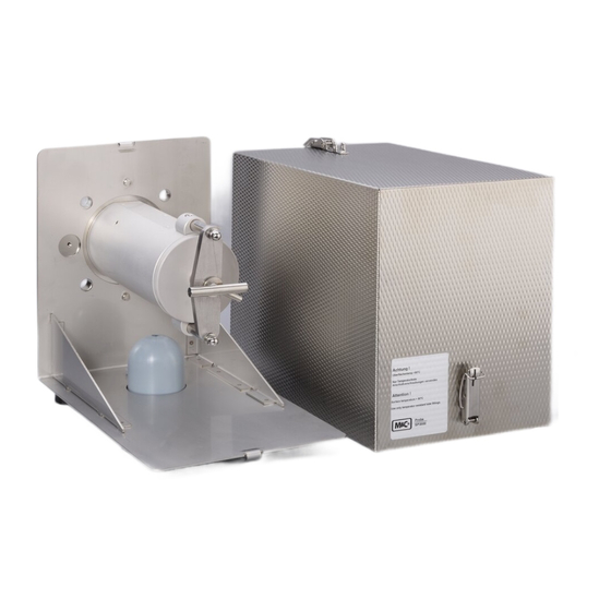
PROBE DESIGN OF THE HEATED VERSION
SAMPLE GAS CONNECTION
Describes the connection for sample lines and its types.
TEMPERATURE CONTROLLER
SAMPLE TUBE AND PREFILTER POSSIBILITIES
RECEIPT OF GOODS AND STORAGE
PREPARATION FOR INSTALLATION
MOUNTING
CHECK OF THE FILTER ELEMENT
Details the procedure to check the filter element's fit.
MOUNTING OF THE SCREWED CONNECTOR AT THE SAMPLE OUTLET
MOUNTING OF PROBE WITH SAMPLE TUBE OR PREFILTER
MOUNTING OF SAMPLE LINE
CONNECTION OF OPTION TEST GAS FEEDING OR BLOW BACK LINE
CONNECTION OPTION PNEUMATIC DRIVE MS1 OR MS3
ELECTRICAL CONNECTIONS
STANDARD VERSION WITH INTERNAL CAPILLARY TUBE THERMOSTAT
Details electrical connections for the standard version.
VERSION WITH PT100 OR THERMOCOUPLE (OPTION)
Describes electrical connections for optional sensors.
STARTING
GAS SAMPLE PROBE SP2300-H
Specific operational notes for the SP2300-H model.
OPTION CALIBRATION GAS FEEDING AND BLOW BACK
Covers calibration gas and blow back options.
OPTION 3/2 WAY BALL VALVE /3VA AND /3VA320
OPTION BALL VALVE DRIVES
OPTION PNEUMATIC DRIVE MS1 OR MS3 WHEN USING A 2/2-WAY BALL VALVE /VA
Connecting pneumatic drives with 2/2-way ball valves.
OPTION PNEUMATIC DRIVE MS1 OR MS3 WHEN USING A 3/2-WAY BALL VALVE /3VA
OPTION ELECTRICAL BALL VALVE DRIVE
OPTION SOLENOID VALVE UNITS FOR BLOW BACK, TEST GAS FEEDING AND CONTROL OF THE PNEUMATIC DRIVES
MAINTENANCE
CHANGING FILTER ELEMENT AND CHECKING SEALINGS
Steps for changing filter elements and checking seals.
CHANGE OF THE OPTIONAL PREFILTER
CHANGE OF HEATING CARTRIDGE AND THERMOSTAT
SWITCHING OFF
PROPER DISPOSAL OF THE DEVICE
SPARE PART LIST
CONNECTION AND MOUNTING DATA
APPENDIX
Table of Contents
Print
Rename the bookmark
Delete bookmark?
Delete from my manuals?
Login
Sign In
OR
Sign in with Facebook
Sign in with Google
Upload manual
Upload from disk
Upload from URL
Need help?
Do you have a question about the SP2000 and is the answer not in the manual?
Questions and answers