Sign In
Upload
Download
Table of Contents
Contents
Add to my manuals
Delete from my manuals
Share
URL of this page:
HTML Link:
Bookmark this page
Add
Manual will be automatically added to "My Manuals"
Print this page
×
Bookmark added
×
Added to my manuals
Manuals
Brands
M&C Manuals
Laboratory Equipment
SP2000-H
Instruction manual
M&C SP2000-H Instruction Manual
Hide thumbs
1
2
Table Of Contents
3
4
5
6
7
8
9
10
11
12
13
14
15
16
17
18
19
20
21
22
23
24
25
26
27
28
29
30
31
32
33
34
35
36
37
38
39
40
41
42
43
44
45
46
47
48
49
50
51
52
53
54
55
56
57
58
59
page
of
59
Go
/
59
Contents
Table of Contents
Bookmarks
Table of Contents
Table of Contents
General Information
Declaration of Conformity
Safety Instructions
Warranty
Used Terms and Signal Indications
Introduction
Serial Numbers
Technical Data
Application
Description
Probe Design of the Heated Version
Sample Gas Connection
Figure 1 Design of Basic Version SP2000-H
Temperature Controller
Sample Tube and Prefilter Possibilities
Receipt of Goods and Storage
Preparation for Installation
Mounting
Check of the Filter Element
Figure 2 Mounting Possibilities SP2000
Figure 3 Cross-Sectional Drawing SP2000-H
Mounting of the Screwed Connector at the Sample Outlet
Figure 4 Removing the New Filter Housing Lid
Figure 5 Mounting of Screwed Connector at Sample Outlet
Mounting of Probe with Sample Tube or Prefilter
Figure 6 Mounting of Sample Tube or Prefilter
Mounting of Sample Line
Figure 7 Mounting of Heated Sample Line
Connection of Option Test Gas Feeding or Blow Back Line
Figure 8 Connection Test Gas Feeding or Blow Back Line
Connection Option Pneumatic Drive MS1 or MS3
Electrical Connections
Standard Version with Internal Capillary Tube Thermostat
Version with PT100 or Thermocouple (Option)
Figure 9 Electrical Connection for SP2000-H, SP2300-H and SP2400-H with Thermostat Controller
Figure 10 Electrical Connection of External Temperature Controller E.g. 70304G
Starting
Figure 11 Electrical Connection Electronic Controller 70304G
Gas Sample Probe SP2300-H
Option Calibration Gas Feeding and Blow Back
Option Check Valve /R
Option 3/2 Way Ball Valve /3VA and /3VA320
Figure 12 Calibration Gas Feeding
Option Ball Valve Drives
Option Pneumatic Drive MS1 or MS3 When Using a 2/2-Way Ball Valve /VA
Figure 13 Pneumatic Drive for 2/2-Way Ball Valve
Option Pneumatic Drive MS1 or MS3 When Using a 3/2-Way Ball Valve /3VA
Figure 14 Pneumatic Drive for 3/2-Way Ball Valve
Option Electrical Ball Valve Drive
Option Solenoid Valve Units for Blow Back, Test Gas Feeding and Control of the Pneumatic Drives
Figure 15 Electrical Connection for Electrical Ball Valve Drive
Figure 16 Connections Solenoid Valve Unit 2
Figure 17 Connections Solenoid Valve Unit 3
Option Drive Unit 234B for the Solenoid Valve Units
Figure 18 Wiring Plan of Control Unit 234B
Maintenance
Changing Filter Element and Checking Sealings
Figure 19 Filter Elements and Gaskets
Change of the Optional Prefilter
Change of Heating Cartridge and Thermostat
Figure 20 Position of Thermostat and Heating Cartridge
Figure 21 Position of Fixing Screws of Connection Box, Thermostat Sensor and Heating Cartridge Carrier Plate
Figure 22 Dismounted Electrical Connection Box with Heating Cartridge and Thermostat Sensor
Switching off
Proper Disposal of the Device
Figure 23 Adjustment of the Mechanical Stop at the Thermostat Controller
Spare Part List
Connection and Mounting Data
Appendix
Figure 24 SP2000-H Basic Version
Figure 25 SP2000-H with Options
Sp2300-H
Figure 27 SP2300-H Filter Elements
Figure 28 High Temperature Tube Aluminium Oxide AO
Figure 29 Heated Sample Tubes SP30-H
Figure 30 Test Gas Feeding and Blow Back Possibilities
Figure 31 SP2000-H/3VA/MS-NC-B
Figure 32 SP2000-H/3VA/MS-NC-C
Figure 33 SP2000-H/3VA/MS-NO-B
Figure 34 SP2000-H/3VA/MS-NO-C
Advertisement
Quick Links
Download this manual
®
Gas Sample Probe Series SP
SP2000, SP2000-H, SP2300-H,
SP2400-H
serial number 10283 and higher
Instruction Manual
Version 1.00.03
Table of
Contents
Previous
Page
Next
Page
1
2
3
4
5
Advertisement
Table of Contents
Need help?
Do you have a question about the SP2000-H and is the answer not in the manual?
Ask a question
Questions and answers
Related Manuals for M&C SP2000-H
Laboratory Equipment M&C SP Series Instruction Manual
(59 pages)
Laboratory Equipment M&C SP Series Instruction Manual
Gas sample probe (26 pages)
Laboratory Equipment M&C SP2000 Instruction Manual
(59 pages)
Laboratory Equipment M&C CSS Series Instruction Manual
Gas conditioning unit, 19“, wall mount or portable in carrying case with software version 1.6 (59 pages)
Laboratory Equipment M&C CSS Series Instruction Manual
19“ housing or wall mounting gas conditioning unit (36 pages)
Summarization of Contents
GENERAL INFORMATION
CE Certification
Product complies with EU directives for electromagnetic compatibility and low voltage.
DECLARATION OF CONFORMITY
SAFETY INSTRUCTIONS
WARRANTY
USED TERMS AND SIGNAL INDICATIONS
Danger Hazard
Indicates potential death, severe injury, or significant material damage if safety measures are ignored.
Warning Hazard
Indicates potential death, severe injury, or material damage if safety measures are not followed.
Caution Hazard
Indicates potential minor injuries or material damage if safety measures are not followed.
Attention Note
Highlights important information requiring user attention.
General Note
Provides additional information about the product or manual.
Qualified Personnel Definition
Defines personnel qualified for installation, use, and maintenance of the product.
Corrosive Hazard Warning
Warns about substances that destroy tissue and equipment, advising on handling.
Hot Surface Warning
Warns about hot surfaces, indicating potential burns upon contact.
High Voltage Warning
Alerts to high voltages and the need for protection against damages.
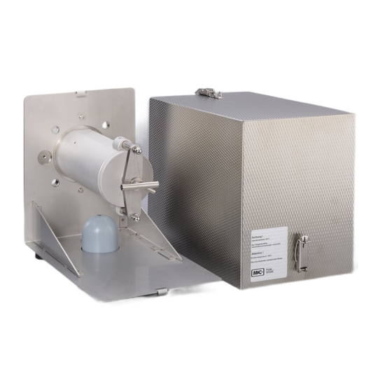
INTRODUCTION
SERIAL NUMBERS
TECHNICAL DATA
APPLICATION
DESCRIPTION
Probe Design of Heated Version
Explains the construction of heated probes, including filter housing, flange, and connection box.
Sample Gas Connection
Describes how to connect sample lines to the probe's outlet, including thread types and versions.
Temperature Controller
Explains the standard capillary thermostat and options for external sensors like PT100.
Sample Tube and Prefilter Possibilities
Lists available sample tubes and prefilters with their specifications and materials.
RECEIPT OF GOODS AND STORAGE
PREPARATION FOR INSTALLATION
Mounting Flange Connection Options
Details flange connection standards and optional adapter flange options.
MOUNTING
Filter Element Check
Procedure for checking the filter element's tight fit before installation.
Filter Housing Lid Removal
Detailed steps for opening and closing the filter housing lid to access the filter element.
Sample Outlet Connector Mounting
Instructions for mounting the screwed connector onto the probe's sample outlet.
Probe, Sample Tube, and Prefilter Mounting
Guidance on attaching sample tubes or prefilters to the probe, including flange seals and adapters.
Sample Line Mounting
Steps for connecting the sample line to the probe's sample gas outlet.
Test Gas Feeding and Blow Back Line Connection
How to connect lines for test gas feeding or blow back.
ELECTRICAL CONNECTIONS
Standard Thermostat Probe Connection
Electrical connection for probes with integrated thermostat.
External Sensor Probe Connection
Electrical connection for probes using external temperature sensors.
External Temperature Controller Wiring
Wiring details for connecting the external temperature controller.
STARTING
SP2300-H Operation Notes
Specific operational notes for the SP2300-H probe model.
Calibration and Blow Back Procedures
Procedures for using calibration gas and blow-back functions.
Ball Valve and Actuator Options
Details on ball valve types, pneumatic/electric drives, and their connections.
Solenoid Valve Unit Configurations
Description of solenoid valve units, including examples for units 2 and 3.
Clock Generator and Time Delay Relay Functions
Explains the function and adjustment of clock generators K2/K3 and time delay relay K1 for back purging.
Ball Valve Position Operations
Explains operation for NC and NO ball valve positions.
MAINTENANCE
Filter Element and Seal Replacement
Step-by-step guide for replacing filter elements and checking seals.
Optional Prefilter Change
Procedure for removing and changing the prefilter.
Heating Cartridge and Thermostat Replacement
Instructions for replacing the heating cartridge and thermostat.
Connection Box Component Removal
Identifying screw locations and procedures for removing connection box components.
Thermostat Mechanical Stop Adjustment
How to adjust the mechanical stop on the thermostat to set the maximum temperature.
SWITCHING OFF
PROPER DISPOSAL OF THE DEVICE
SPARE PART LIST
CONNECTION AND MOUNTING DATA
APPENDIX
Table of Contents
Print
Rename the bookmark
Delete bookmark?
Delete from my manuals?
Login
Sign In
OR
Sign in with Facebook
Sign in with Google
Upload manual
Upload from disk
Upload from URL
Need help?
Do you have a question about the SP2000-H and is the answer not in the manual?
Questions and answers