CAME FROG Installation Manual
Hide thumbs
Also See for FROG:
- Installation manual (65 pages) ,
- Installation manual (49 pages) ,
- Installation manual (12 pages)
Table of Contents
Advertisement
Quick Links
Advertisement
Table of Contents

Related Manuals for CAME FROG


Summary of Contents for CAME FROG
- Page 1 Swing-gate operator FA01722-EN FROG FROG-X INSTALLATION MANUAL English...
- Page 3 Machinery Directive (2006/42/EC) and with the reference harmonised technical standards are specified in the general CAME product catalogue or on the website www.came.com. • Make sure the mains power supply is disconnected during all installation procedures. • Check that the temperature ranges given are suitable for the installation site. • The appliance must be powered with a voltage corresponding to the value shown on the rating plate.
- Page 4 • If the product malfunctions, stop using it and contact an authorised support centre. If the production batch is not immediately identifiable, please contact customer services. The general conditions of sale are given in the official CAME price lists. Main points of danger for people No transiting while the barrier is moving.
-
Page 5: Intended Use
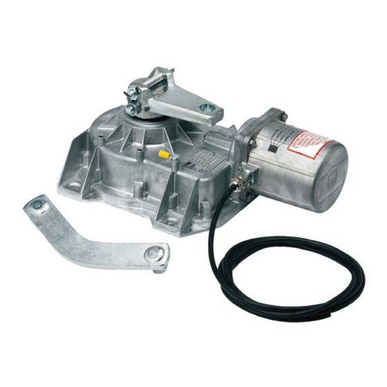
Underground brushless irreversible 24 V gearmotor with standard encoder, Adaptive Speed & Torque Technology, movement management, obstacle detection and adjustable leaf-stop during closing, for swing gates with leaves up to 4 m in length and 400 kg in weight. FROG-X is controlled by the relevant control panel 801QA-0090. Intended use Concealed solution for use in residential and apartment block settings Any installation and/or use other than that specified in this manual is forbidden. -
Page 6: Usage Limitations
(**) The average product life specified should be understood purely as an indicative estimate. It applies to normal usage conditions and where the product has been installed and maintained in compliance with the instructions provided in the CAME technical manual. The average product life is also affected, including significantly, by other variables such as, but not limited to, climatic and environmental conditions. -
Page 7: Installation
INSTALLATION The following illustrations are examples only. The space available for fitting the operator and accessories varies depending on the area where it is installed. It is up to the installer to find the most suitable solution. Preliminary operations The preliminary operations for installation concern the foundation box installation and the release devices fastening. Refer to the installation manuals for these products. - Page 8 Lubricate the transmission lever. Fit the transmission lever as shown in the drawings. Determining the travel end points with mechanical limit switches Open the leaf to the desired point. The leaf maximum opening is 110°. Unscrew the opening limit-switch point adjustment screw until it touches the foundation box. Tighten the nut to lock the screw into position.
-
Page 9: Electrical Connections
ELECTRICAL CONNECTIONS Before working on the control panel, disconnect the mains power supply and remove the batteries, if any. Provide IP67 junction boxes with terminal blocks for connections. Gear motor with encoder Gearmotor delayed while opening Red cable Gearmotor delayed while closing Grey cable Junction box Black cable... -
Page 10: Final Operations
FINAL OPERATIONS OUTWARDS OPENING The operations other than the standard installation are described below. Setting up the gearmotor Insert the closing limit-switch point adjustment screw into the gearmotor arm. Gearmotor installed on the left Gearmotor installed on the right... - Page 11 Electrical connections Before working on the control panel, disconnect the mains power supply and remove the batteries, if any. Provide IP67 junction boxes with terminal blocks for connections. Gear motor with encoder Gearmotor delayed while opening Red cable Gearmotor delayed while closing Grey cable Junction box Black cable...
- Page 12 Check the release mechanism is working efficiently by performing a manoeuvre with the leaf free. The gate leaf must not be obstructed. Check the cables are intact and connected correctly. AFFIX THE PRODUCT LABEL FROM THE BOX HERE CAME S.p.A. Via Martiri della Libertà, 15 31030 Dosson di Casier Treviso - Italy Tel.
Need help?
Do you have a question about the FROG and is the answer not in the manual?
Questions and answers