Sign In
Upload
Manuals
Brands
Gotting Manuals
Marine Radio
HG G-71451-A
User Manuals: Gotting HG G-71451-A Transponder-Antenna
Manuals and User Guides for Gotting HG G-71451-A Transponder-Antenna. We have
2
Gotting HG G-71451-A Transponder-Antenna manuals available for free PDF download: Manual
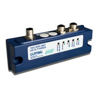
Gotting HG G-71451-A Manual (78 pages)
Transponder-Antenna
Brand:
Gotting
| Category:
Marine Radio
| Size: 2 MB
Table of Contents
Table of Contents
3
About this Document
6
Warning Notices
6
Table 1 Hazard Classification According to ANSI Z535.6-2006
6
Symbols
7
Definitions of Terms
7
Abbreviations
8
Introduction
9
Variants
9
Table 2 Variant Overview
9
Additional Products
10
Table 3 Additional Products
10
Operating Conditions
11
Additional Documents
11
Application Examples for the Automation
12
System Layout
12
Functional Description
12
General Functional Description
12
Figure 1 Block Diagram System Layout
12
Scope and Function
13
Figure 2 Detection Area 1 and 2, Data-Free Area D and Nominal Reading Distance
13
Figure 3 Detection Areas, Top View
14
Figure 4 Core Area of the Reading Antenna with Position Impulse (Top View)
14
Signals and Timing
15
Figure 5 Signals and Timing
15
Switch-On Behavior
16
Posipulse
16
Code Output
16
Applies to All Variants
16
Hardware
16
Transponder
16
Transponder Antenna (Variants)
16
Transponder Antenna HG G-71450 (RS 232)
17
Pin Assignments
17
Figure 6 Connection Options Posipulse
17
Figure 7 HG G-71450: Housing Dimensions Transponder Antenna
17
Table 4 HG G-71450: Pin Assignment of the 5 Pin Circular Connector ST 1, Male, A-Coded
17
Serial/Parallel Interface HG G-06150Y (Optional)
18
Figure 8 HG G-71451: Housing Dimensions of the Transponder Antenna
18
Transponder Antenna HG G-71451-A (Profibus)
18
Table 5 HG G-71450: Meaning of the 4 Leds
18
RS 232-Interface
18
Switch-On Behavior
18
Leds
18
Code Output
18
Pin Assignments
19
Leds
19
Table 6 HG G-71451: Pin Assignment of the 5 Pin Circular Connector ST1, Male, A-Coded
19
Table 7 HG G-71451: Pin Assignment of the 5 Pin Circular Connector ST2, Female, B-Coded
19
Table 8 HG G-71451: Pin Assignment of the 5 Pin Circular Connector ST3, Male, B-Coded
19
Table 9 HG G-71451: Meaning of the 5 Leds
19
Pin Assignments
20
Table 10 HG G-71453: Pin Assignments of the 5 Pin Circular Connector ST1 (Pin)
20
Figure 9 HG G-71453: Housing Dimensions Transponder Antenna
20
Switch-On Behaviour
20
Transponder Antenna HG G-71453-A (Canopen®)
20
RS 232-Interface
20
Profibus-Interface
20
Table 11 HG G-71453: Pin Assignment of the 5 Pin Circular Connector ST2 (Socket)
21
Table 13 Meaning of the 5 Leds
21
Table 12 HG G-71453: Pin Assignment of the 5 Pin Circular Connector ST3 (Pin)
21
Leds
21
Posipulse Filter
21
RS 232-Interface
21
Data Interface Canopen
21
Transponder Antenna HG G-71455-A (Profinet)
22
Pin Assignments
22
Figure 10 HG G-71455: Housing Dimensions Transponder Antenna
22
Table 14 HG G-71455: Pin Assignments of the 5 Pin Circular Connector ST 1 (Pin)
22
Table 15 HG G-71453: Pin Assignment of the 4 Pin Circular Connector ST 2 & ST 3 (Socket)
22
Leds
23
Data Interface Profinet
23
USB Interface
23
Table 16 Meaning of the 5 Leds
23
Transponder Antenna
24
Testing Transponder
24
Installation and Commissioning
24
Installing Transponder
24
Mounting Holes
25
Connection Cable
25
Figure 12 Nominal Reading Distances / Position of the Antenna Ferrite Rods / Metal- Free Space
25
Interface HG 06150Y (Optional for HG G-71450)
26
Figure 13 Structure of the Interface Mounting Bar Housing
26
Table 17 Pin Assignment of the Interface Mounting Bar Housing
26
Commissioning
27
Interfaces: RS 232/Serial (HG G-71450)
28
Interface Parameter RS 232
28
Figure 14 HG G-71450: Position of the DIP-Switches SW1 to SW8 on the Antenna Board
28
Table 18 HG G-71450: Configuration Options Via the DIP-Switches of the Antenna Board
28
Table 20 HG G-71450: Example Telegram ASCII-Coded
29
Telegram Setup ASCII Coding (SW5 = ON)
29
Table 19 HG G-71450: Baud Rate Adjustment Via SW2 and SW3
29
Figure 15 HG G-71450: Example for a ASCII Telegram Setup
29
Telegram Setup of Binary Coding (SW5 = OFF)
30
Resetting the Antenna
30
Transponder Programming
30
Figure 16 HG G-71450: Example for a Binary Telegram Setup
30
Table 21 HG G-71450: Example Telegram Binary Coded
30
Serial/Parallel Interface HG G-06150Y (Optional)
31
Figure 17 HG G-71450: Optional Interface HG G-06150Y for Mounting Bar Installation
31
Table 22 HG G-71450: Setting DIP Switches 1 to 5 for Using. Serial/Parallel Interfaces
31
Table 24 HG G-71451: Structure of the Profibus Output Bytes
32
Table 23 HG G-71451: Structure of the Three Profibus Input Bytes
32
Profibus Configurations
32
Profibus Address (Hex Rotary Switch)
32
Interfaces: Profibus (HG G-71451)
32
Status and Command Bits
33
Transponder Programming
33
Table 25 HG G-71451: Structure of the 3 Profibus Output Bytes
33
Table 26 HG G-71451: Meaning of the Status Bits
33
Table 27 HG G-71451: Meaning of the Command Bits
33
GSD File
34
Interfaces: Canopen® (HG G-71453)
35
Definitions CAN and Canopen
35
Table 28 CAN: Parameter PDO Operating Mode
35
Table 32 Canopen® Operating Mode
36
Table 30 Definitions Can/Canopen
36
Table 31 CAN: Bit and Byte Sequences
36
Table 29 CAN: PDO Operating Modes
36
Node ID
37
Default Values
37
Description of the Transmission Process Data Objects (TPDO)
37
Table 33 HG G-71453: CAN Factory Settings
37
Table 34 HG G-71453: Structure CAN Transmitting Object TPDO_1
37
Description of the Receiving Process Data Objects (RPDO)
38
Heartbeat
38
Table 35 HG G-71453: Description of the Status Bits
38
Table 36 HG G-71453: CAN Receiving Object RPDO_1
38
Table 37 HG G-71453: Coding of the Node Status
38
Table 39 HG G-71453: Communication Specific Entries in the Range from 0X1000 to 0X1Fff
39
Object Directory
39
Description of the Service Data Objects (Sdos)
39
Table 38 HG G-71453: SDO Telegram Error Codes
39
Table 40 HG G-71453: Manufacturer Specific Entries at 0X2000
40
Table 41 HG G-71453: Standardised Device Profile Area in the Range from 0X6000 to 0X6400
40
Table 42 HG G-71453: Device Type
41
Table 43 HG G-71453: Error Register
41
Table 44 HG G-71453: Manufacturer Device Name
41
Table 45 HG G-71453: Canopen® Directory: Hardware Version
41
Table 46 HG G-71453: Canopen® Directory: Software Version
41
Table 47 HG G-71453: Save Parameter
41
Table 48 HG G-71453: Restore Default Parameter
42
Table 49 HG G-71453: Producer Heartbeat Time
42
Table 50 HG G-71453: Identity Object
42
Table 51 HG G-71453: RPDO_1 Parameter
42
Table 54 HG G-71453: Mapping TPDO_1
43
Table 52 HG G-71453: Mapping RPDO_1
43
Table 53 HG G-71453: Transmit PDO_1 Parameter
43
Table 55 HG G-71453: Manufacture Parameter
44
Manufacture Parameters - Node Parameters
45
Table 57 HG G-71453: CAN: Coding of the Node Baud Rate
45
Table 58 HG G-71453: CAN: Coding of the Node Config Bytes
45
Table 56 HG G-71453: CAN: Manufacture Parameters - Node Parameters
45
Table 59 HG G-71453: 8 Bit Digital Inputs (Transmitted in TPDO 1)
45
Table 60 HG G-71453: 16 Bit Digital Inputs
45
Transponder Programming
46
EDS File
46
Table 61 HG G-71453: 16 Bit Digital Inputs
46
Table 63 HG G-71455: Structure of the Profinet Output Bytes
47
Table 62 HG G-71455: Structure of the Profinet Input Bytes
47
Output Bytes
47
Input Bytes
47
Interfaces: Profinet (HG G-71455)
47
Status Bits
48
Instruction Bits
48
Transponder Programming
48
GSDML File
48
Table 64 HG G-71455: Description of the Profinet Status Bits
48
Table 65 HG G-71455: Description of the Profinet Command Bits
48
Software / Configuration
49
Connection to a PC
49
Via the Serial Interface (HG G-71450 / HG G-71451 / HG G-71453)
49
Figure 18 Connection Example RS 232: Connection with the Serial Interface of a
49
Table 66 Transmission Parameters of the Serial RS232 Interface
50
Figure 19 Connection Example RS 232: Connection with the Serial Interface of a
50
Via the USB Interface (HG G-71455)
50
Terminal Program
51
Logging (CSV Output)
51
Table 67 Variants of the Transponder Antenna with Logging Function
51
Monitor Program (Service)
52
Table 68 Description of the Values Output Via CSV
52
Main Menu Monitor Program HG G-71450
53
Main Menu Monitor Program HG G-71451
53
Figure 20 HG G-71450: Main Menu of the Monitor Program
53
Figure 21 HG G-71451: Main Menu of the Monitor Program
53
Monitor Program HG G-71453
54
Main Menu
54
P)Osi Filter
54
Figure 22 HG G-71453: Main Menu of the Monitor Program
54
CAN Menu
55
Figure 23 HG G-71453: CAN Menu
55
Main Menu Monitor Program HG G-71455
56
Figure 24 HG G-71455: Main Menu of the Monitor Program
56
Table 69 Default Values Profinet Interface HG G-71455
56
Update of the Operating Software (Firmware)
57
About the RS 232 Interface (HG G-71450 / HG G-71451 / HG G-71453)
57
Figure 25 Output of the Firmware Version (for Example HG G-71450)
57
Figure 26 Screen Request for ASCII-Upload (for Example HG G-71450)
57
Via the USB Interface (HG G-71455)
58
Figure 27 HG G-71455: Firmware Update - Choose File
59
Figure 28 HG G-71455: Firmware Update - Start the Update
59
Figure 29 HG G-71455: Firmware Update - Leave DFU Mode
59
Figure 30 Notes for Transponder Programming
61
Positioning of the Transponders Using HG G-71325 as an Example
61
Transponder Programming
61
Programming Via the Monitor Program
62
Programming Via Interface Telegrams
62
HG G-71450: Programming Via Serial Telegrams
62
Structure of the Telegram (Host -> Antenna)
63
Table 70 HG G-71450: Content of the Telegrams Sent by the Host (ASCII Mode)
63
Table 71 HG G-71450: Content of the Telegrams Sent by the Host (Binary Mode)
63
Structure of the Telegram (Antenna -> Host / if Transponder Is Not Programmed)
64
HG G-71451: Programming Via Profibus Telegrams
64
HG G-71453: Programming Via Canopen® Telegrams
64
HG G-71455: Programming Via Profinet Telegrams
64
Table 72 HG G-71450: Contents of the Telegrams Sent by the Antenna
64
Table 73 HG G-71450: Content of the Telegrams Sent by the Antenna (Binary Mode)
64
Maintenance
66
Troubleshooting
67
Table 74 Troubleshooting
67
Technical Data
69
Transponder Antenna
69
Table 75 Technical Data Transponder Antenna
69
Parallel Converter
70
Table 76 Technical Data Parallel Converter HG G-06150Y (Optional for HG G-71450)
70
List of Figures - Chapter 14 71 List of Figures
71
List of Figures
71
List of Tables
72
Index
74
Copyright
76
Copyright and Terms of Liability
76
Exclusion of Liability
76
Trade Marks and Company Names
76
Advertisement
Gotting HG G-71451-A Manual (76 pages)
Transponder-Antenna
Brand:
Gotting
| Category:
Antenna
| Size: 3 MB
Table of Contents
Table of Contents
3
Table 1 Hazard Classification According to ANSI Z535.6-2006
6
About this Document
6
Warning Notices
6
Abbreviations
7
Symbols
7
Definitions of Terms
7
Variants
8
Table 2 Variant Overview
8
Introduction
8
Additional Products
9
Table 3 Additional Products
9
Additional Documents
10
Operating Conditions
10
Application Examples for the Automation
10
Figure 1 Block Diagram System Layout (Example)
11
General Functional Description
11
System Layout
11
Functional Description
11
Scope and Function
12
Figure 2 Detection Area 1 and 2, Data-Free Area D and Nominal Reading Distance S, Side View
12
Figure 3 Detection Areas, Top View
12
Figure 4 Core Area of the Reading Antenna with Positioning Pulse (Top View)
13
Signals and Timing
14
Figure 5 Signals and Timing
14
Switch-On Behavior
15
Posipulse
15
Switch-Off Behavior
15
Code Output
15
Applies to All Variants
15
Transponder Antenna (Variants)
15
Transponder
15
Hardware
15
Figure 7 HG G-71450: Housing Dimensions Transponder Antenna
16
Table 4 HG G-71450: Pin Assignment of the 5 Pin Circular Connector ST 1, Male, A-Coded
16
Transponder Antenna HG G-71450 (RS 232)
16
Figure 6 Connection Options Posipulse
16
Pin Assignments
16
Leds
17
RS 232-Interface
17
Serial/Parallel Interface HG G-06150XA (Optional)
17
Transponder Antenna HG G-71451-A (PROFIBUS®)
17
Figure 8 HG G-71451: Housing Dimensions of the Transponder Antenna
17
Table 5 HG G-71450: Meaning of the 4 Leds
17
Table 7 HG G-71451: Pin Assignment of the 5 Pin Circular Connector ST2, Female, B-Coded
18
Table 9 HG G-71451: Meaning of the 5 Leds
18
Table 8 HG G-71451: Pin Assignment of the 5 Pin Circular Connector ST3, Male
18
Table 6 HG G-71451: Pin Assignment of the 5 Pin Circular Connector ST1, Male
18
Leds
18
Pin Assignments
18
Switch-On Behaviour
19
PROFIBUS®-Interface
19
RS 232-Interface
19
Transponder Antenna HG G-71453-A (Canopen®)
19
Pin Assignments
19
Figure 9 HG G-71453: Housing Dimensions Transponder Antenna
19
Table 10 HG G-71453: Pin Assignments of the 5 Pin Circular Connector ST1 (Pin)
19
Table 11 HG G-71453: Pin Assignment of the 5 Pin Circular Connector ST2 (Socket)
20
Table 13 Meaning of the 5 Leds
20
Table 12 HG G-71453: Pin Assignment of the 5 Pin Circular Connector ST3 (Pin)
20
RS 232-Interface
20
Posipulse Filter
20
Data Interface Canopen
20
Leds
20
Table 14 HG G-71455: Pin Assignments of the 5 Pin Circular Connector ST 1 (Pin)
21
Table 15 HG G-71455: Pin Assignment of the 4 Pin Circular Connector ST 2 & ST 3 (Socket)
21
Transponder Antenna HG G-71455-A (PROFINET®)
21
Pin Assignments
21
Figure 10 HG G-71455: Housing Dimensions Transponder Antenna
21
Leds
22
Data Interface PROFINET
22
USB Interface
22
Table 16 Meaning of the 5 Leds
22
Installing Transponders
23
Testing Transponders
23
Installation and Commissioning
23
Mounting / Minimum Distances
24
Figure 11 Installing the Antenna: Position and Size of the Mounting Holes (in the Picture Variant HG G-71455)
24
Figure 12 Nominal Reading Distances / Position of the Antenna Ferrite Rods / Metal- Free Area
24
Transponder Antenna
24
Variants with 409 Khz in Connection with Energy Tracks
25
Connection Cables
25
Interface HG 06150XA (Optional for HG G-71450)
25
Figure 13 Minimum Distances in Facilities with Inductive Energy Transmission Sys
25
Commissioning
26
Figure 14 HG G-71450: Position of the DIP-Switches SW1 to SW8 on the Antenna Board
27
Table 17 HG G-71450: Configuration Options Via the DIP-Switches of the Antenna Board
27
Interface Parameter RS 232
27
Interfaces: RS 232/Serial (HG G-71450)
27
Table 19 HG G-71450: Example Telegram ASCII-Coded
28
Telegram Setup ASCII Coding (SW5 = ON)
28
Table 18 HG G-71450: Baud Rate Adjustment Via SW2 and SW3
28
Figure 15 HG G-71450: Example for a ASCII Telegram Setup
28
Telegram Setup of Binary Coding (SW5 = OFF)
29
Resetting the Antenna
29
Transponder Programming
29
Figure 16 HG G-71450: Example for a Binary Telegram Setup
29
Table 20 HG G-71450: Example Telegram Binary Coded
29
Serial/Parallel Interface HG G-06150XA (Optional)
30
Figure 17 HG G-71450: Optional Interface HG G-06150Y for Mounting Bar Installation
30
Table 21 HG G-71450: Setting DIP Switches 1 to 5 for Using. Serial/Parallel Interfaces
30
Table 23 HG G-71451: Structure of the PROFIBUS® Output Bytes
31
Table 22 HG G-71451: Structure of the Three PROFIBUS® Input Bytes
31
PROFIBUS® Configurations
31
PROFIBUS® Address (Hex Rotary Switch)
31
Interfaces: PROFIBUS® (HG G-71451)
31
Status and Command Bits
32
Transponder Programming
32
Table 24 HG G-71451: Structure of the 3 PROFIBUS® Output Bytes
32
Table 25 HG G-71451: Meaning of the Status Bits
32
Table 26 HG G-71451: Meaning of the Command Bits
32
GSD File
33
Interfaces: Canopen® (HG G-71453)
34
Definitions CAN and Canopen
34
Table 27 CAN: Parameter PDO Operating Mode
34
Table 31 Canopen® Operating Mode
35
Table 28 CAN: PDO Operating Modes
35
Table 30 CAN: Bit and Byte Sequences
35
Table 29 Definitions Can/Canopen
35
Node ID
36
Default Values
36
Description of the Transmission Process Data Objects (TPDO)
36
Table 32 HG G-71453: CAN Factory Settings
36
Table 33 HG G-71453: Structure CAN Transmitting Object TPDO_1
36
Description of the Receiving Process Data Objects (RPDO)
37
Table 34 HG G-71453: CAN Transmitting Object TPDO_1 - Description of the Status Bits
37
Table 35 HG G-71453: Structure CAN Receiving Object RPDO_1
37
Table 36 HG G-71453: CAN Receiving Object RPDO_1 - Description of the Command Bits
37
Table 38 HG G-71453: SDO Telegram Error Codes
38
Table 37 HG G-71453: CAN Coding of the Device Status
38
Description of the Service Data Objects (Sdos)
38
Heartbeat
38
Object Directory
39
Table 39 HG G-71453: Communication Specific Entries in the Range from 0X1000 to 0X1Fff
39
Table 40 HG G-71453: Manufacturer Specific Entries at 0X2000
40
Table 41 HG G-71453: Standardised Device Profile Area in the Range from 0X6000 to 0X6400
40
Table 42 HG G-71453: Device Type
40
Table 43 HG G-71453: Error Register
40
Table 44 HG G-71453: Manufacturer Device Name
40
Table 45 HG G-71453: Canopen® Directory: Hardware Version
40
Table 49 HG G-71453: Producer Heartbeat Time
41
Table 50 HG G-71453: Identity Object
41
Table 48 HG G-71453: Restore Default Parameter
41
Table 47 HG G-71453: Save Parameter
41
Table 46 HG G-71453: Canopen® Directory: Software Version
41
Table 51 HG G-71453: RPDO_1 Parameter
42
Table 52 HG G-71453: Mapping RPDO_1
42
Table 53 HG G-71453: Transmit PDO_1 Parameter
42
Table 54 HG G-71453: Mapping TPDO_1
43
Table 55 HG G-71453: Manufacture Parameter
43
Manufacture Parameters - Node Parameters
44
Table 57 HG G-71453: CAN: Coding of the Node Baud Rate
44
Table 58 HG G-71453: CAN: Coding of the Node Config Bytes
44
Table 56 HG G-71453: CAN: Manufacture Parameters - Node Parameters
44
Table 59 HG G-71453: 8 Bit Digital Inputs (Transmitted in TPDO 1)
44
Table 60 HG G-71453: 16 Bit Digital Inputs Transponder Code
44
Table 62 HG G-71453: 16 Bit Digital Outputs Transponder Code
45
EDS File
45
Table 61 HG G-71453: 8 Bit Digital Outputs Command Code
45
Transponder Programming
45
Interfaces: PROFINET® (HG G-71455)
46
Input Bytes
46
Output Bytes
46
Table 63 HG G-71455: Structure of the PROFINET® Input Bytes
46
Table 64 HG G-71455: Structure of the PROFINET® Output Bytes
46
Status Bits
47
Command Bits
47
Transponder Programming
47
GSDML File
47
Table 65 HG G-71455: Description of the PROFINET® Status Bits
47
Table 66 HG G-71455: Description of the PROFINET® Command Bits
47
Figure 18 Connection Example RS 232: Connection with the Serial Interface of a
48
Via the Serial Interface (HG G-71450 / HG G-71451 / HG G-71453)
48
Connection to a PC
48
Software / Configuration
48
Via the USB Interface (HG G-71455)
49
Figure 19 Connection Example USB: Connection with the USB Interface of a PC
49
Table 67 Transmission Parameters of the Serial RS232 Interface
49
Terminal Program
50
Logging (CSV Output)
51
Table 68 Variants of the Transponder Antenna with Logging Function
51
Table 69 Description of the Values Output Via CSV
51
Monitor Program (Service)
52
Main Menu Monitor Program HG G-71450
52
Figure 20 HG G-71450: Main Menu of the Monitor Program
52
Figure 22 HG G-71453: Main Menu of the Monitor Program
53
Figure 21 HG G-71451: Main Menu of the Monitor Program
53
Monitor Program HG G-71453
53
Main Menu Monitor Program HG G-71451
53
Main Menu
53
P)Osi Filter
54
CAN Menu
54
Figure 23 HG G-71453: CAN Menu
54
Main Menu Monitor Program HG G-71455
55
Figure 24 HG G-71455: Main Menu of the Monitor Program
55
Table 70 Default Values PROFINET® Interface HG G-71455
55
Update of the Operating Software (Firmware)
56
Via the RS 232 Interface (HG G-71450 / HG G-71451 / HG G-71453)
56
Figure 25 Output of the Firmware Version (for Example HG G-71450)
56
Figure 26 Screen Request for ASCII-Upload (for Example HG G-71450)
56
Via the USB Interface (HG G-71455)
57
Figure 29 HG G-71455: Firmware Update - Leave DFU Mode
58
Figure 27 HG G-71455: Firmware Update - Choose File
58
Figure 28 HG G-71455: Firmware Update - Start the Update
58
Transponder Programming
59
Positioning of the Transponders Using HG G-71325 as an Example
59
Figure 30 Notes for Transponder Programming
59
Programming Via the Monitor Program
60
Programming Via Interface Telegrams
60
HG G-71450: Programming Via Serial Telegrams
60
Structure of the Telegram (Host -> Antenna)
61
Table 71 HG G-71450: Content of the Telegrams Sent by the Host (ASCII Mode)
61
Table 72 HG G-71450: Content of the Telegrams Sent by the Host (Binary Mode)
61
Table 74 HG G-71450: Content of the Telegrams Sent by the Antenna (Binary Mode)
62
Table 73 HG G-71450: Contents of the Telegrams Sent by the Antenna (ASCII Mode)
62
HG G-71453: Programming Via Canopen® Telegrams
62
HG G-71451: Programming Via PROFIBUS® Telegrams
62
Structure of the Telegram (Antenna -> Host / if Transponder Is Not Programmed)
62
HG G-71455: Programming Via PROFINET® Telegrams
63
Maintenance
64
Troubleshooting
65
Table 75 Troubleshooting
66
Technical Data
67
List of Figures - Chapter 14 69 List of Figures
69
List of Figures
69
List of Tables
70
Index
73
Copyright
75
Copyright and Terms of Liability
75
Exclusion of Liability
75
Trade Marks and Company Names
75
Advertisement
Related Products
Gotting HG G-71450-A
Gotting HG G-71453-A
Gotting HG G-71455-A
Gotting HG G-71910-C
Gotting HG G-71912-A
Gotting HG G-71915
Gotting HG G-73650-A
Gotting HG G-76343
Gotting HG G-76344
Gotting HG G-7335 ZB Series
Gotting Categories
Antenna
GPS
Accessories
Controller
Marine Radio
More Gotting Manuals
Login
Sign In
OR
Sign in with Facebook
Sign in with Google
Upload manual
Upload from disk
Upload from URL